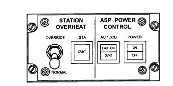
Figure 4-32.-SASP control-indicator.
C-11104/UYS-1 Control-Indicator
The C-11104/UYS-1 control-indicator (fig. 4-32)
consists of one switch-indicator, two indicators, and
one switch. The switch-indicator is labeled POWER
ON/OFF. It controls the power to the SA, the display
computer (DCU), the CASS transmitter, and the
displays. The AU/DCU CAUTION/OVHT indicator
indicates the temperature status in the SA and the
DCU. The CAUTION section will flash on when the
thermal warning is activated in either unit. The
OVHT section indicates an overheat in either unit.
The STA OVHT indicator indicates an overtemp
condition exists at the sensor stations 1 and 2
consoles. The OVERRIDE-NORMAL switch will
override the overheat warnings for the sensor stations
1 and 2 consoles.
REVIEW QUESTIONS
Q1. How was the word SONAR derived?
Q2. In echo-ranging sonar, what is the source of
the sound wave used?
Q3. What are the three main characteristics of
seawater that affect the speed of a sound wave
passing through it?
Q4. On the azimuth and range indicator of the
AN/ASQ-13E, what does the cursor intensity
knob control?
Q5. What is the length of the special-purpose
cable of the AN/ASQ-13E?
Q6. What are the staves of the hydrophone
assembly filled with?
Q7. What is an anomaly?
Q8. What happens to the magnetic field of an
aircraft as it maneuvers?
Q9. How many units are therein the ASA-64 SAD
group?
Q10. With a sonobuoy equipped with EFS, how
many depth settings are available?
4-28