results in three output signals, which are sent to the
ECA. These coils are located in the MAD boom.
COMPENSATION COILS.— There are three
compensating coils located in the boom. These coils
generate the magnetic field that opposes the
aircraft-generated noise fields for compensation.
There is one coil each for the transverse, vertical, and
longitudinal fields.
CP-1390 MAGNETIC FIELD COMPUTER.—
The magnetic field computer, along with the magnetic
field indicator, computerizes the compensation
procedure. The correlation portion of the system, the
2A5 board in the ECA, becomes redundant to the
computer. The magnetic field computer receives the
maneuver signals, MAD signals, and the
potentiometer outputs. From these signals, it
computes the adjustment values for the nine magnetic
terms simultaneously.
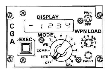
ID-2254 MAGNETIC FIELD INDICATOR.—
The magnetic field indicator (fig. 4-29) allows the
operator to select various weapon loads and initiate
the self-test, auto compensation, and weapon deploy-
ment programs.
It also displays the most recent
computer-calculated term difference value.
The PWR/OFF switch accesses aircraft power.
The DISPLAY indicator is a four-digit numerical
display and a polarity indicator. It shows the various
BITE codes, term values, or calibration values. The
EXEC push button initiates all commands. This
button must be pressed after each selection of the
MODE switch.
Figure 4-29.-ID-2254 magnetic field indicator.
The MODE switch is a 14-position rotary switch
that provides computer identification and control of
fixed compensation functions. The OFF position
means that there are no functions processed. The
BITE position conducts a built-in test and reports the
results via the digital readout. In the COMP position,
pressing the EXEC button conducts the nine-term
compensation program. The WD position enables the
four-term weapon deployment compensation
program.
In the CAL position, a digital value
measurement of the magnetic coils for calibration
accuracy is initiated. The other nine positions report
the most recent computer-calculated term difference
value via the DISPLAY. Remember, after selecting
any of the positions on the MODE switch, the EXEC
button must be pressed.
The FAULT indicator illuminates whenever a
fault condition exists. The WPN LOAD switch is a
nine-position switch labeled 0-8. The number of
weapons being carried is selected on this switch prior
to compensation. This provides compensation for at
least 80 percent of the weapons interference field.
AN/ASA-71 Selector Control Group
The selector control group consists of two units.
These units are the MAD selector control panel and
the selector control subassembly.
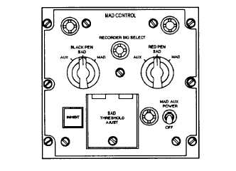
C-7693/ASA-71 SELECTOR CONTROL
PANEL.— This selector control (fig. 4-30) selects the
signal to be recorded on the MAD recorder and
adjusts the threshold voltage for the SAD system.
The two knobs labeled BLACK PEN and RED PEN
Figure 4-30.-C-7693/ASA-71 selector control panel.
4-23