compensation is needed for the longitudinal axis and
is provided for by the development of outrigger
compensators of Permalloy near the detecting
element.
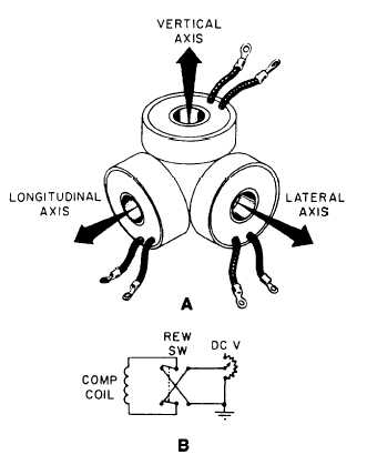
Permanent field compensation must be done in
three dimensions rather than in two, and it is
accomplished by three compensating coils mounted
mutually perpendicular to each other (fig. 4-25, view
A). The aircraft is rotated in 5-degree and 10-degree
steps around its three axes. Adjustment of the field
strength is accomplished by controlling the amount of
direct current that flows through a particular coil.
Figure 4-25, view B, shows a circuit for a single
compensating coil.
Compensation for the dc magnetic field is
accomplished by using electromagnetic compensating
loops. The loops are arranged to provide horizontal,
vertical, and longitudinal fields, and they are adjusted
to be equal and opposite to the dc magnetic field
caused by the load current. The compensating loops
are connected across a variable resistor for a
particular distribution center, and they are adjusted to
allow current flow proportional to the load current for
correct compensation. Different types of aircraft
Figure 4-25.-A. Arrangement of compensating colts.
B. Compensating coil circuit.
have several sets of compensation loops, depending
upon the number of distribution centers. In newer
aircraft, production changes have been made to use
ground return wires to minimize loop size.
The procedure for adjustment of the dc com-
pensation system makes use of straight and level
flight on the four cardinal headings. For example,
actuation of a cowl flap motor will cause dc field
changes representative of those caused by any nacelle
load. The load is energized, the size and polarity of
the signal are noted, and the compensation control is
adjusted. The load is reenergized, and the com-
pensation control is adjusted again. Adjustments are
continued until the resulting signals from the dc field
are minimized.
Under ideal conditions, all magnetic fields that
tend to act on the magnetometer head would be
completely counterbalanced. In this state the effect
on the magnetometer is the same as if there were no
magnetic fields at all. This state exists only when the
following ideal conditions exist:
1. The aircraft is flying a steady course through a
magnetically quiet geographical area.
2. Electric or electronic circuits are not turned on
or off during compensation.
3. Direct current of the proper intensity and
direction has been set to flow through the com-
pensation coils, so that all stray fields are balanced.
To approximate these conditions, the com-
pensation of MAD equipment is usually performed in
flight, well at sea.
In this way, the equipment is
compensated under operation conditions, which
closely resemble those of actual ASW search flights.
From the foregoing, it should be clear that the
objective of compensation is to gain a state of total
balance of magnetic forces around the magnetometer.
Thereafter, any sudden shift in one of the balanced
forces (such as an anomaly in the earth’s field force)
upsets the total balance. This imbalance is indicated
on the recorder. Unfortunately, a shift in ANY of the
balanced forces will be indicated. Shift in any of the
forces other than the earth’s natural field are regarded
as noise.
MAJOR COMPONENTS
The MAD system consists of the AN/ASQ-81
MAD set, AN/ASA-64 submarine anomaly detecting
(SAD) group, AN/ASA-65 magnetic compensator
4-20