group, AN/ASA-71 selector control group, and the
RO-32/ASQ MAD recorder.
AN/ASQ-81 MAD Set
The AN/ASQ-81 set consists of the DT-323
magnetic detector, the AM-4535 amplifier-power
supply, and the C-6983 detecting set control box.
DT-323 MAGNETIC DETECTOR.— The
detection element includes six separate helium
absorption cells and six IR detectors, arranged in
pairs, with the pairs oriented at 90° to each other.
This configuration ensures that one or more of the
pairs is at least partially in line with the earth’s field
regardless of aircraft attitude or direction of flight.
The signals from all three detector pairs are combined
in a summing amplifier. The final output to the
amplifier-power supply is not affected by aircraft
maneuvers because of the arrangement.
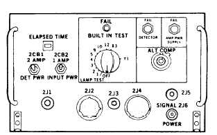
AM-4535 AMPLIFIER-POWER SUPPLY.—
The amplifier-power supply (fig. 4-26) serves two
purposes. The first purpose is the power supply
portion. This section provides the necessary power to
the MAD subsystem. The amplifier section contains
the necessary electronics to detect the anomaly signal
from the detector output signal.
There are three fail indicators on the amplifier-
power supply. The FAIL light comes on when there is
a fault in the assembly being tested with the BITE
switch. The FAIL DETECTOR and the FAIL AMP
PWR SUPPLY lights indicate failure of the magnetic
detector or the amplifier-power supply. The ALT
COMP dial is used to vary the amplitude of the
altitude compensation signal. The BUILT IN TEST
switch provides a self-test of quick replaceable
assemblies in the amplifier-power supply. The two
circuit breakers provide circuit protection for the dc
power to the magnetic detector and the 115-volt ac
power to the amplifier-power supply.
On the right side of the amplifier-power supply,
there is a hinged door that covers a maintenance
panel. When this door is closed, the equipment
operates in the normal mode. On the maintenance
panel there is a RES OSC ADJ switch that is used to
manually adjust the resonance oscillator frequency
during maintenance procedures. There is also a
MODE SELECT switch that selects various system
configurations necessary for proper maintenance and
troubleshooting.
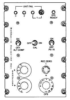
C-6983 CONTROL BOX.— The detecting set
control box (fig. 4-27) contains the operating switches
and indicators for the MAD system. Across the top of
the faceplate are five indicators that indicate faults in
the other units. The indicator labeled 3 indicates a
magnetic detector failure when lit. The indicator
labeled 2 indicates amplifier failure. The next two
indicators indicate a control box fault. The SYS
READY indicator illuminates when the system is
ready for operation. This indicator will blink during
warm-up.
There are three toggle switches across the middle
portion of the control box. The one on the right is the
power switch.
This switch applies power to the
system. The middle switch is labeled CAL. It selects
the calibration signal for use. The switch on the left is
Figure 4-26.-AM-4535 amplifier-power supply.
Figure 4-27.-C-6893 detecting set control.
4-21