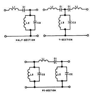
Figure 10-11.-Low-pass filter circuit.
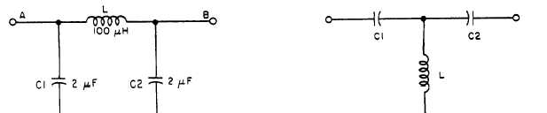
Figure 10-12.-Schematic diagram of a high-pass filter section.
and C2 must withstand the line voltage. Therefore,
filters are also rated as to maximum voltage.
At frequencies immediately below cutoff, the filter
looks capacitive to both the generator and the load.
Inductive reactance XL has very little influence, and no
filtering action takes place. However, at frequencies
above cutoff, the series reactance of coil L becomes
increasingly higher. The series reactance of coil L is
limited only by the resistance of the coil and its
distributed capacitance.
Coil L then functions as a
high-frequency disconnect. The bypass values of both
C1 and C2 become increasingly higher, and are limited
only by the inductance of the capacitors and their leads.
As a result of these two actions, high-frequency
isolation between points A and B is achieved.
High-Pass Filters
In almost all radio transmitters operating at high
frequencies (HF) and above, the master oscillator
signal is generated at a submultiple of the output
frequency. By use of one or more frequency
multipliers, the basic oscillator frequency is raised to
the desired output frequency. At the input to the
antenna, an overdriven output amplifier may output
the output frequency and harmonics of the output
frequency. A high-pass filter is very effective in
preventing the undesired harmonics from reaching the
antenna and being radiated.
High-pass filters are also useful for isolating a
high-frequency receiver from the influence of energy
of signals of lower frequencies. Figure 10-12 shows a
typical high-pass filter being used to reduce
radio-noise interference. In symmetrical high-pass
filter sections (Zin = Zout), the series combination of
C1 and L should resonate at @ times the desired
cutoff frequency. The L/C ratio that is chosen should
have a square root equal to the terminal impedance.
Bandpass Filters
Bandpass filters provide a very high impedance
above and below a desired band of frequencies within
that band.
Bandpass filters find their greatest
application in the following reamer:
Decoupling the receiver from shock and
overload by transmitters operating above and
below the receiver band
Multiplexing and decoupling two or more
receivers or transmitters using the same
antenna
A bandpass filter can be one of many forms and
configurations, depending upon its application. For
filtering antennas, a bandpass filter normally consists of
one or more high-pass filter sections, followed by one or
more low-pass filter sections. The configuration of
sections is normally selected so the upper limit of the
pass band approaches or exceeds twice the frequency of
the lower limit of the pass band. Figure 10-13 shows
typical arrangements for bandpass filters.
Figure 10-13.-Examples of bandpass filter circuits.
10-13