the signal applied to it. These spurious frequencies
are called “external cross-modulation.”
These
spurious frequencies (sum, difference, and
harmonics) can be expected to cause interference
problems when the combined product of their field
strengths exceed 1 millivolt.
A common example of this action is the entry of a
strong off-frequency RF voltage into the mixer stage
of a superheterodyne receiver.
By the time the
interfering signal has passed through the preselector
stages of the receiver, it has undergone distortion by
clipping.
Therefore, the interfering signal is
essentially a rectangular wave that is rich in
harmonics. Frequency components of the wave beat
both above and below the local oscillator frequency
and its harmonics, and produce, at the output of the
mixer, signals that are acceptable to the IF amplifier.
POWER LINES
Alternating current power sources have already
been briefly discussed as broadband interference.
Even though they are conducting a nearly sinusoidal
waveform, ac signals on power lines are capable of
interfering with audio signals in receivers. In such
cases, only the power-line frequency appears.
However, where multiple sources of ac power are
present, these signals are capable of being mixed in
the same manner as discussed under receiver
oscillators. Sum and difference frequencies appear.
In at-powered equipment, ac hum can appear at
the power frequency or at the rectification ripple
frequency. The rectification ripple frequency is twice
the power frequency times the number of phases.
Normally, aircraft systems use only single- and
three-phase sources at a nominal 400 Hz. Full-wave
rectification with single-phase 400-Hz power gives a
ripple frequency of 800 Hz. A three-phase source
would give a 2400 Hz ripple. This ripple produces
interference varying from annoyance to complete
unreliability of equipment, depending upon the
severity and its coupling to susceptible elements.
Openings in the outer shields of equipment are
necessary for the entrance of power leads, control
leads, mechanical linkages, ventilation, and antenna
leads.
Interference entering these openings is
amplified by various amounts, depending upon the
point of entry into the equipment’s circuits. Coupling
between the entry path and the sensitive points of the
receiver can be in any form.
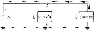
CONDUCTIVE COUPLING
Interference is often coupled from its source to a
receiver by metallic conduction. Normally, this is
done by way of mutual impedance, as shown in
figure 10-1. Note in the figure that A is the power
source, B the receiver, and C the interference source.
The interference is maximum at the interference
source (C), and attenuates rapidly to a relatively low
value at the battery (A). This occurs because of the
very low impedance of the battery. It is apparent from
the size of the arrows that the nearer the power tap of
the receiver (B) to the interference source (C), the
greater the amplitude of interfering current in the BC
loop.
INDUCTIVE-MAGNETIC COUPLING
Every current-carrying conductor is surrounded
by a magnetic field whose intensity variations are
faithful reproductions of variations in the current in
the conductor. When another parallel conductor is cut
by the lines of force of this field, the conductor has a
current induced into it. The amplitude of the induced
current depends upon the following factors:
The strength of the current in the first
conductor
The nearness of the conductors to each other
The angle between the conductors
The length through which the conductors are
exposed to each other
INTERFERENCE COUPLING
Learning Objective:
Identify the various
types of electrical interference caused by
coupling, and recognize the means used to
reduce the interference.
Figure 10-1.-Path of conducted interference.
10-6