INTERCOMMUNICATION SYSTEM
(ICS)
Learning Objective:
Recognize components
and operating features of an inter-
communication system used in naval aircraft.
The intercommunication system that will be
discussed in this section is the OK-248( )(V)/AI,
Intercommunication-Communication Control Group
(ICCG). This system is found on the S-3 aircraft.
The OK-248( )(V)/AI provides intercommuni-
cations for crew members and maintenance personnel.
It also controls operation and signal interfacing for all
radio sets, and controls operation and signal interfacing
for aural monitoring of the navigation aids.
MAJOR COMPONENTS
The following is a discussion on the various com-
ponents in the OK-248( )/AI system.
C-8760/AI Intercommunication-
Communication Control Panel
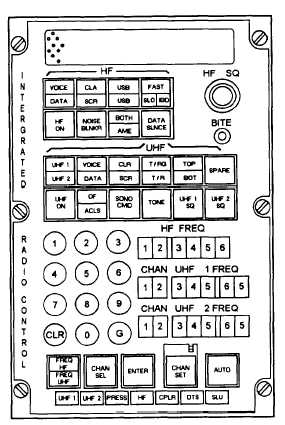
The C-8760/AI (fig. 1-1) is commonly called the
integrated radio control (IRC). The IRC panel performs
the following functions:
Controls HF radio modes and functions
Controls UHF radio modes and functions
Displays In-Flight Performance Monitor (IFPM)
status of communication subsystems and
components
Initiates on-line operating configuration of
communication systems
There are eight switches for the HF system function
selections, along with a squelch knob. These switches
are used to select the various modes of operation for the
HF system on board. The squelch knob is turned
clockwise to increase squelch and counterclockwise to
decrease squelch.
The next section of switches (labeled UHF) on the
IRC panel are used to control the UHF radios. There are
twelve of these switches but only eleven are used. The
switch labeled SPARE is not used.
The next section consists of a numerical keyboard,
five switches, and three sets of indicators. The keyboard
is where the operator inputs the desired channel and
frequencies for the HF and UHF radios. The CLR button
Figure 1-1.-C-8760/AI intercommunication-communication
control panel.
is used to clear an error and start over with the selection.
The G button is used to select a guard channel. The three
indicator groups display the following:
HF FREQ—displays the selected frequency for
the HF radio set
CHAN UHF 1 FREQ—displays the selected
channel and frequency for the UHF 1 radio set
CHAN UHF 2 FREQ—displays the selected
channel and frequency for the UHF 2 radio set
The five switches are used to select what type of
information the operator is inputting via the keyboard.
After the operator inputs the channel or frequency, the
ENTER switch must be pressed.
The last section of the panel contains seven fault
indicator lights. These indicators are labeled UHF1,
UHF2, PRESS, HF, CPLR, DTS, and SLU. Each one is
the fault indicator for the system or component for
which it is labeled. It will illuminate when a fault occurs
in its corresponding system or component.
Located directly under the HF squelch knob is a
BITE indicator. This indicator will illuminate when a
fault is detected in the IRC.
1-3


