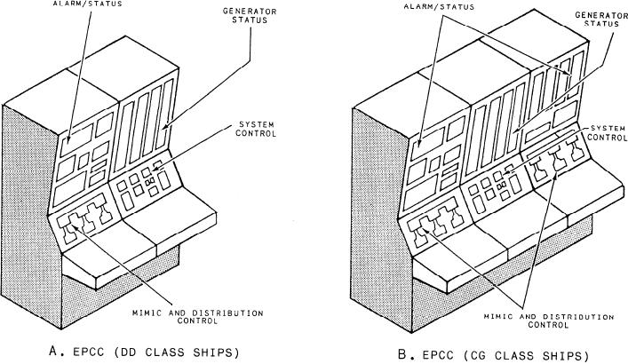
sequence the operation of equipment or to control sub-
9. 400-HZ power system
s y s t e m operation. The operation of the electrical
We will briefly discuss these control systems. For a
distribution systems equipment is normally controlled
detailed description of the operation of these systems,
from the EPCC.
we recommend you refer to the EOSS, the EOP, and the
The EPCC contains the controls and indicators that
appropriate technical manuals.
are used to remotely operate and monitor the ship's
service power generation and distribution systems.
GTGS Monitoring
Figure 3-6 shows that each panel of the EPCC is
dedicated to particular types of control and monitoring,
Each GTGS has sensors to provide remote
based on the class of ship. (See views A and B.) Notice
monitoring of the gas turbine engine and the generator.
in view B that the EPCC on the CG-47 class ships has
The sensor information is sent to the EPCC in one of the
an additional section for the 400-Hz system. In this
three following ways:
section, we will take a look at the following control
systems:
1. Directly from alarm contact switches
1 . GTGS monitoring
2. Through alarm detector circuits in the generator
control panel
2 . Electrical distribution system monitoring
3. Through the PAMISE via the S/CE No. 1
3 . Circuit breaker control
The PAMISE provides the high vibration alarm and
4 . Gas turbine control
parameter information for the demand display indicator
5. Generator control
(DDI).
6. System configurations
There are several GTGS alarms at the EPCC that
indicate abnormal conditions to the operator. With two
7 . Load shedding
exceptions, these alarms are initiated by contact sensors
8 . TOPS
at the GTGS. The alarms that are not initiated by contact
Figure 3-6.--EPCC layout.
3-16

