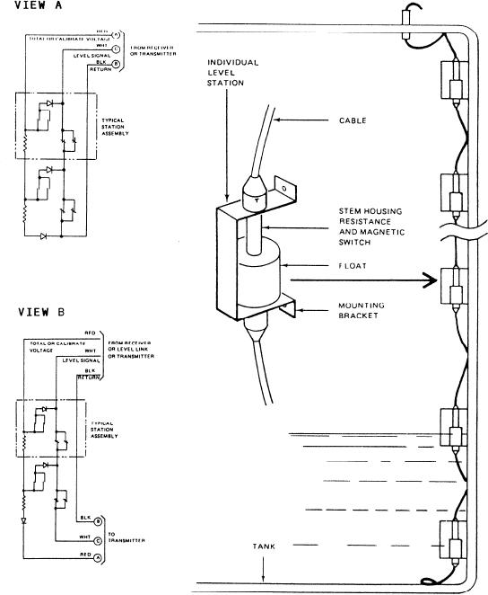
Figure 6-13.--Link transmitter float assembly.
rubber and potted in a mylar tube. The tube is
Receiver devices are used to convert the electrical
surrounded by a neoprene tube and is mounted inside a
signals generated by the level detection devices into
stainless-steel tube. Electrical leads connect the resistors
deflections of a pointer on a meter. The meter is usually
marked in gallons. Primary receiver modules perform
and magnetic reed switches to electrical connectors
located either at the top, bottom, or both ends of the
level indication, alarm generation, and alarm indication
functions for one tank. A receiver panel provides the
transmitter.
same function for several tanks.
Now study the link transmitter float assembly
shown in figure 6-13. The link system (views A and B)
The magnetic float system is operated by the
can be used alone or in combination with transmitter
changing liquid level in the tank. As the liquid level
assemblies. Each level link system includes several
changes, the float moves up or down the transmitter.
cable-connected station assemblies. Individual station
Figure 6-14 shows how bar magnets in the float operate
assemblies include magnet-equipped floats that ride up
t a p switches in a two-at-a-time, three-at-a-time,
and down on stems. Each stem houses a resistor,
two-at-a-time closing sequence as the float moves up the
magnetic reed switches, and a semiconductor diode. A
transmitter. When two adjacent tap switches are closed,
mounting bracket is provided on the stem for individual
the effective electrical tap point on the voltage divider
mounting of each station assembly of the system.
network is halfway between the two switches. As the
6-12

