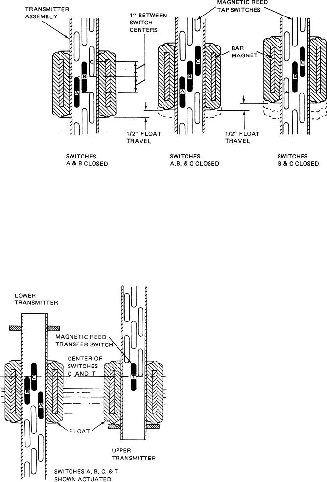
Figure 6-14.--Transmitter tap switch operational sequence.
closed. As a result, voltage drops are read in 1/2-inch
float closes the next tap switch (the first two are still
closed), the effective tap point is halfway between the
increments of float travel.
first and third tap switches; that is, it is at the middle
When two or more transmitters are installed in a
switch. This middle point is 1/2 inch from the effective
tank, each transmitter except the bottom transmitter has
tap point established when only two tap switches were
a transfer switch. These switches are of the type shown
in figure 6-15. The transfer switch is a magnetically
operated reed switch. It is connected between the
common conductor (to the tap switch resistances) in one
transmitter and the common conductor in the next lower
transmitter. The transfer switch is held closed when the
float on its transmitter is at the bottom limit. As the float
level rises with the fluid level, the transfer switch opens
and disconnects the tap switches in the lower transmitter.
The transfer switch action is required to open the
common conductor circuit to the lower transmitter tap
switches. The uppermost tap switch of the lower
transmitter tap switches is held closed now, since the
lower transmitter float is at its top limit of travel. The
resulting voltage change produced by the changing tank
level is processed by the receiver module, and the liquid
level is indicated on the meter.
The liquid-level switches on board your class of
ship may differ somewhat. However, the principle of
operation will be similar to the one just discussed. For
s p e c i f i c operational characteristics, refer to the
manufacturer's technical manual for the system on your
Figure 6-15.--Overlapped transmitter transfer switch
operation.
ship.
6-13

