Regulating valve
A control valves manifold block assembly,
mounted on the side of the OD box, contains
Blades and blade bolts
control valves for both manual and automatic
(electronic) pitch control. The manual control
valves consist of a manual pitch control
Crankpin rings
valve and two manual changeover valves.
Blade seal base rings
Automatic pitch control is accomplished through
an electrohydraulic control oil servo valve. This
Tailshaft spigot
valve responds to an electrical signal generated
from the shipboard electronics.
Blade port covers
HUB/BLADE ASSEMBLY
Hub cone cover and hub cone end cover
The hub/blade assembly provides the mount-
ing for the five propeller blades and contains the
Hub Body Assembly
hydraulic servomotor mechanism for blade pitch
control. It also transforms propulsion shaft
Propeller blade pitch is hydraulically con-
rotational torque into axial thrust for ship
trolled by the hydraulic servomotor. The servo-
motor, consisting of the piston, the piston rod
propulsion. The hub body is secured to the
tailshaft flange by 15 bolts and 5 dowel pins. The
assembly, and the regulating valve, is contained
rotational torque of the propulsion shaft is
within the hub body. A one-piece crosshead is
transmitted to the hub by the five dowel pins. The
secured to the forward end of the piston rod. The
hub/blade assembly has the following major
hub body forms the crosshead chamber with the
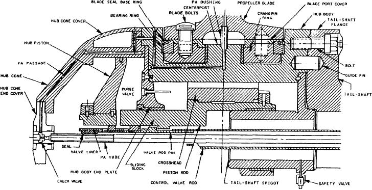
components (fig. 8-21):
tailshaft spigot enclosing the forward end of the
chamber and the hub body end plate enclosing
Hub body assembly
the aft end. The servomotor cylinder is formed
by the hub body end plate and the hub cone. The
Piston and piston rod assembly
piston rod extends through the bore in the hub
Crosshead and sliding blocks
body end plate into the crosshead chamber.
Figure 8-21.--Cross-sectional view of the hub/blade assembly.
8-31

