
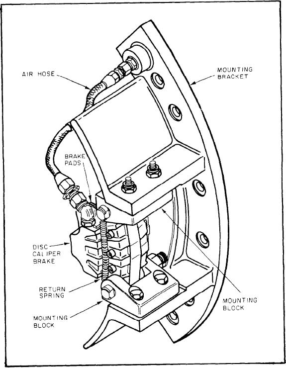
self-adjusting, they always maintain the proper
FFG Turbine Brakes
clearance.
The brakes are controlled by individual
Each input shaft is equipped with a single
solenoid valves in the turbine brake panel so they
disc caliper brake assembly. Figure 8-16 shows a
may be engaged independently of each other. The
typical turbine brake assembly. Each brake is
solenoid valves are controlled electrically at the
pneumatically operated and is self-retracting. The
PCC and the LOP. The valves may be actuated
brake includes two brake pads, one on each
manually at the turbine brake panel (fig. 8-17).
side of the brake disc. Since the brakes arc
Figure 8-16.--Typical turbine brake assembly.
8-26