
propellers produce what we call inboard rotation.
Figure 8-l shows a typical MRG. This figure
That is, when viewed from the propeller end look-
does not show the MRG in the proper perspective
ing forward, the port shaft should rotate clockwise
as to size. A typical MRG is 15.5 feet long, 16.75
feet wide, 13 feet high, and can weigh as much
and the starboard shaft should rotate counter-
as 57.5 tons (115,000 pounds).
clockwise. The GTEs all rotate in the same
Multiple shaft ships have special needs when
direction. This requires the MERs to be arranged
it comes to the design of the power train. To
with the port and starboard MRGs installed in
reverse directions with respect to each other. This
prevent steering problems or a tendency for the
provides the required inboard shaft rotation. For
stern section of the ship to walk in the direction
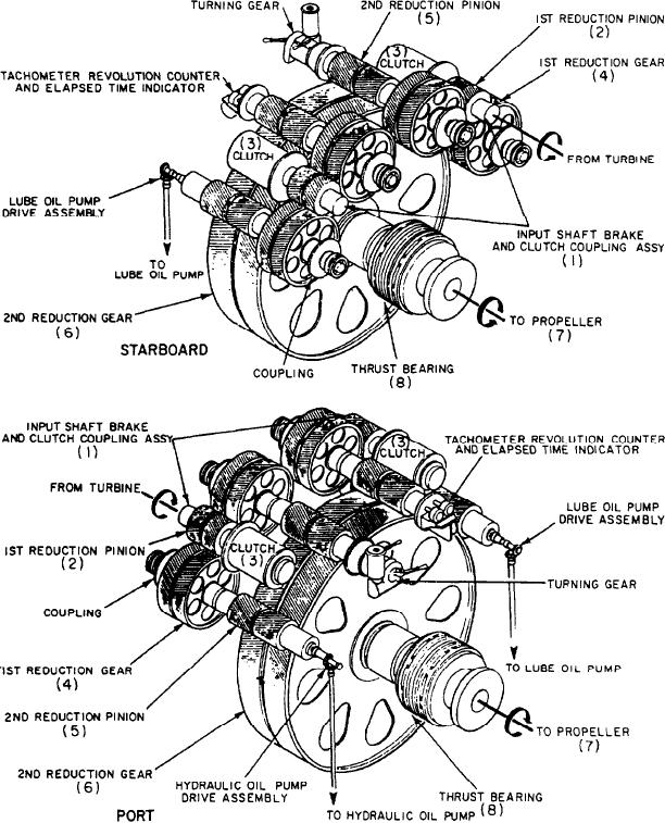
clarity, figure 8-2 shows the rotating elements of
of shaft rotation requires that the shafts and
Figure 8-2.--Rotating elements.
8-3