All gear elements, except for the input shafts
BULL GEAR
and first-reduction pinions, are supported by
conventional babbitt-lined sleeve bearings. The
The bull gear has double helical teeth that are
bearing bores are machined concentric to the out-
driven by the four second-reduction pinions. It
side diameter and are designed for rebabbitting.
may also be driven singly by either two port or
Each bearing is marked with its crown thickness
two starboard second-reduction pinions. The bull
at the time of manufacture. Bearing shells are
gear shaft is mounted in two sleeve bearings. A
made in halves and doweled, serialized, and match
pivoted shoe thrust bearing directs the propeller
marked to ensure proper assembly. Oil spreader
shaft thrust, and its resulting thrust on the bull
grooves are machined at the joints. Oil is admitted
gear and shaft assembly, to the foundation. A
to the bearing surfaces through passages at the
second function of this thrust bearing is to main-
split line and distributed axially along the
tain axial position of the bull gear and shaft
journal by the spreader groove. Grooves are
assembly.
provided at the ends of the spreader grooves to
A split bearing cap is provided for the thrust
allow the flushing of foreign particles out of the
bearing. One half of the bearing cap contains
bearing area. Holes are tapped in the bearing
provisions for mounting a sight flow indicator for
shells for inserting lifting eyes. Antirotation pins
monitoring the flow of lube oil to the bearing.
are used to position the bearing shells at installa-
The other half of the bearing cap contains two
tion and to prevent axial movement or rotation
RTE connecters for remote monitoring of the
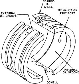
of the bearing shell during operation. Figure 8-4
operating temperature of the ahead and reverse
shows the construction of a typical sleeve bearing.
shoes of the thrust bearing. One of the RTE
elements is located in the forward shoe and one
The journal bearings, supporting the input
is located in the aft.
shafts and first-reduction pinions, are the tilt-pad
type. Since these two elements are the interface
BEARINGS
between the MRG and the engines, they are
susceptible to gear misalignment resulting from
Rotating elements of the MRG (input shafts,
shaft motion and/or momentary minor misalign-
HS pinions, second-reduction pinions, bull gear,
ment caused by ship motion. The self-aligning
and so forth) are supported by bearings secured
feature of the tilt-pad bearing corrects for this
by bearing caps. They are called journal (sleeve)
misalignment. Additionally, the tilt-pad bearing
or tilt-pad bearings. The bearings (or bearing) that
will dampen incipient shaft whip. For more
evenly distribute the axial and radial torque of the
detailed information on the tilt-pad bearing,
propeller shaft are called main thrust bearings.
A removable bearing cap is provided for each
bearing. The bearing caps contain provisions for
mounting sight flow indicators for monitoring the
flow of lube oil to the bearings. Each bearing is
designed in two halves so the bearing can be
removed without removing the shaft. One half of
each bearing contains an RTE that monitors the
operating temperature of the bearing.
Journal Bearings
The bearings supporting the first-reduction
gears, second-reduction pinion, and second-
reduction gear are split in half and doweled
together. The shells are steel with a tin-based
babbitt lining for the bearing surface. Drilled
passages through the shell and lining provide a
flow path for lube oil. Reliefs in the babbitt
lining extend from the oil supply port to the
ends of the bearing. This arrangement assures
distribution of lube oil across the full surface of
the journal.
Figure 8-4.--Construction of a typical sleeve bearing.
8-6

