mounted on the gear case transmits clutch status
SYNCHRO-SELF-SHIFTING CLUTCH
as ENGAGED/DISENGAGED to the control
consoles. A hydraulic locking feature is provided
Identical positive drive SSS clutches connect
in the design to prevent inadvertent clutch
the GTEs to the MRG power train. Each clutch
disengagement during normal transient or shock
is supported by the input shaft and the HS pinion
conditions. A local visual indicator indicates
couplings. The clutches permit operation with
clutch status (ENGAGED or DISENGAGED).
either one or both GTEs driving the propeller.
They also permit changing GTE combinations
Two microswitches (situated in pairs for double-
while the MRG continues to rotate. The clutches
pole changeover action) are provided in each
clutch to give remote indication of these positions.
are fully automatic, free-wheeling devices. They
The clutch is lubricated from an oil supply shaft
transmit torque (power) through splines and gear
teeth machined in the clutch elements without
mounted in the HS pinion bore.
external controls. Clutch engagement is initiated
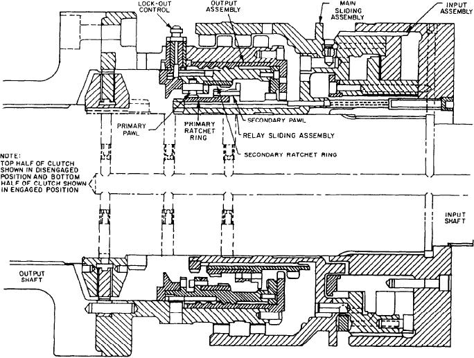
The SSS clutch has an input assembly, a main
by a pawl and ratchet mechanism.
sliding assembly, a relay sliding assembly,
and an output assembly. Figure 8-8 is a
Figure 8-7 shows a clutch assembly. A
cross-sectional view of the clutch showing
manually operated lockout device prevents clutch
the primary components. The clutch also has a
engagement when actuated. The associated GTE
status indicator switch mechanism not indicated
can then be operated independently of the rest of
in figure 8-8.
the power train. An indicator/switch unit
Figure 8-8.--SSS clutch (primary components).
8-11

