
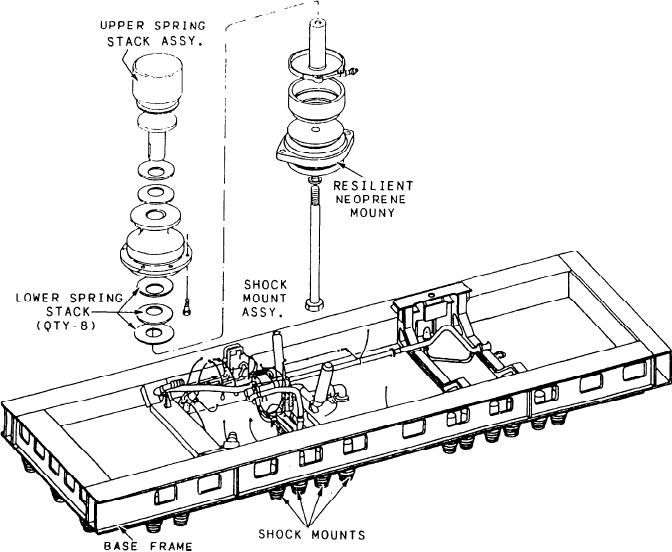
Figure 2-4.--LM2500 GTE base frame and shock mounts (exploded view).
BASE ASSEMBLY
The GTE and the exhaust duct are attached
to the base by 11 supports (fig. 2-5) that secure
the GTE vertically, laterally, and axially. The
The base assembly (fig. 2-4) has a fabricated
steel frame of steel double I-beams to provide a
support to the base attachment points are shimmed
to align the GTE. The forward end of the GTE
stable platform for the GTE. It contains suitable
mounts and links to secure the GTE. Thirty-two
is supported by a large yoke and two supports
shock mounts under the base secure the entire
attached at the compressor front frame (points
base/enclosure assembly to the ship's foundation.
A and G on fig. 2-5). The aft end is attached by
four supports--three on the right side and one on
The shock mounts have two stacks of spring
washers aligned above, and attached to, a resilient
the left (shown on fig. 2-5 at points B, C, and F).
The exhaust duct is secured by two supports (point
neoprene shock mount. They weaken shock loads
by absorbing most of the abrupt up and down
E) on each side and one support (point D) and
a thrust pin (point H) underneath. Figure 2-5 also
movements of the ship's foundation. The base
shows an exploded view of each support point
also provides for connection of electrical, air,
corresponding to its position on the base
services. This area is known as the base
assembly.
penetration plate. More detailed descriptions of
NOTE: All GTE and enclosure references to
the functions of the components that enter the
left, right, front (forward), rear (aft), and clock
enclosure are provided throughout this chapter.
2-4