
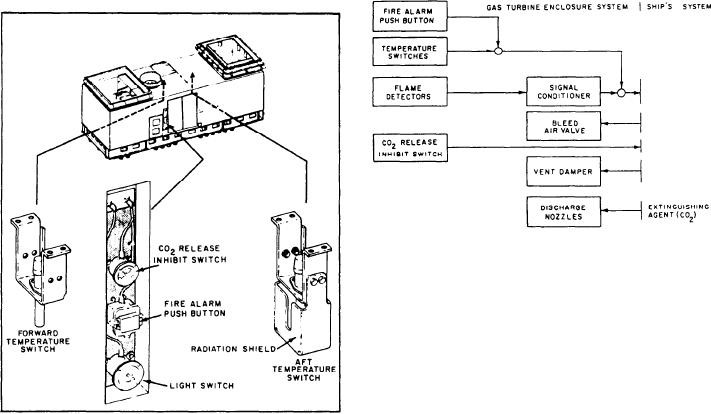
Figure 2-9.--CG, DD, and fire stop sequence flow
chart.
Two CO2 discharge nozzles are located inside
the enclosure. They are mounted on the crossbeam
under the compressor front frame. One is for
initial discharge (primary) and the other for
extended discharge (secondary). The fire extinguish
release/inhibit switch is mounted above the fire
alarm push button. It is a two-position switch
(ACTIVE/INACTIVE). When in the INACTIVE
Figure 2-8.--Fire system temperature switches and manual
position, this switch prevents discharge of the CO2
switches.
extinguishing agent.
Figure 2-9 is a signal flow chart of the fire
turbine module (GTM), which results in the alarm
indication.
stop sequence. Fire is sensed by the flame
detectors or temperature switches. The fire
The two temperature switches are mounted on
may also be discovered by watch station personnel
who would operate the manual CO2 release
the enclosure ceiling and generate an alarm signal
switch. In either situation, the sequence of
if the temperature reaches a preset level (fig. 2-8).
The output of the RTEs, which generate a fire
events are the same after the fire is discovered.
Electrical contacts close to activate the fire-
signal only, is an input to the free standing
extinguishing system and the following concurrent
electronic enclosure (FSEE).
actions occur:
1. The fire alarm signal sounds.
CG-, DD-, and Class Ships
2. The system conducts a self-check to see if
Since we discussed the components of the fire
battle override has been selected at the
detection system in the previous section, we will
propulsion local control console (PLCC)
not discuss them here. The alarm system also has
or the propulsion auxiliary control console
a manual fire alarm push button (shown in
(PACC) or if the module cooling system
fig. 2-8) besides the electrical signal generated
has failed. Either event will terminate the
by either the temperature switch or the flame
fire stop sequence.
detector signal conditioner. The extinguishing
system has two CO2 discharge nozzles. When
3. The GTE fuel shutdown valves close,
manually activated, the CO2 fire-extinguishing
shutting down the GTE.
agent is discharged into the enclosure. It also has
an extinguish release/inhibit switch and a CO2
4. The fuel supply to the GTM is shut off in
release/inhibit switch mounted to the outside of
the ship's service system.
the enclosure, next to the side access door.
2-8