
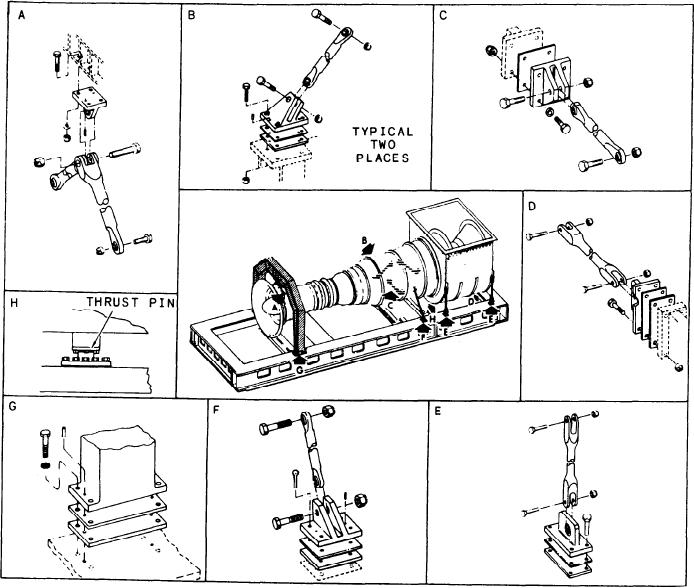
Figure 2-5.--Gas turbine assembly mounting.
positions apply when viewing the GTE from the
explosionproof and fireproof. The inner wall is
rear (exhaust end) looking forward.
constructed of perforated metal and can withstand
a temperature of 2000F for 15 minutes.) With
ventilation air being supplied to the enclosure, the
ENCLOSURE
temperature of the outer wall normally does not
exceed 150F. The right and left propulsion GTE
Refer to figure 2-3 as we discuss the enclosure.
modules are functionally identical. The only
It is a soundproof, fire-resistant housing in which
difference between the enclosures of the different
the GTE operates. The enclosure provides
class ships is their access to the engine.
thermal and acoustical insulation, inlet and
exhaust ducting, and a controlled environment for
the GTE. Flexible coupling joints are provided at
Lighting
the air inlet and exhaust ducts which allow a flow
path/interface between the enclosure and the
Enclosure illumination is provided by nine
ship's ducting. The enclosure is of double-wall
explosionproof light fixtures--eight on the
construction. (NOTE: For personnel safety,
ceiling and one on the base. With the exception
testing was conducted to ensure the enclosure is
o f the CGs module illumination is the
2-5