
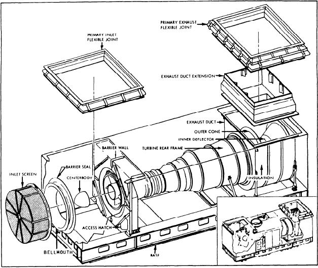
Figure 2-11.--GTE air inlet and exhaust.
4. An inlet duct, which is bell-shaped and
Figure 2-11 shows the air inlet and exhaust
attached to the front frame of the compressor.
components of a GTE. We will discuss the exhaust
The duct, or bellmouth, smoothes the airflow
system after we describe the intake system.
entering the turbine. A flexible seal is attached
between the inlet duct and the barrier wall.
The intake section of the enclosure is
composed of five parts:
5. A dome-shaped faring, called the center-
body, which is attached to the compressor front
1. A primary inlet flexible joint, which
frame hub to aid in smoothing the airflow.
connects the ship's ducting with the enclosure. It
has an upper and lower flange and a fiber-filled
flexible boot.
CG, DD, AND INLET
2. A barrier wall, which has four stainless steel
DUCT SYSTEMS
panels bolted together. It prevents exhaust and
ventilation air from being drawn into the intake.
The inlet duct systems for the CG-, DD-
It has a removable access hatch for maintenance/
c l a s s ships are very similar. The major
operator personnel access to the inlet plenum.
difference is the sand separators used on the
3. A wire mesh inlet screen (foreign object
ships. Since only the four 993
damage (FOD) screen), which is bolted to the
class ships have the sand separators installed, we
barrier wall and prevents foreign objects from
will not discuss this unique feature.
entering the engine.
2-10