
The model 104 generator lube oil system must
The unique components of each generator are
be manually prelubed only if the GTE has
a slip ring and brush assembly on the model 104
remained idle for 5 days or more. On the model
and a brushless exciter assembly on the model 139.
139 an installed prelube pump is provided for the
This is because the model 104 is a brush-type
initial lubrication to the generator upon each start-
generator and the model 139 is a brushless-type
generator
up.
Generator Space Heater
Generator Lube Oil System
Electric heater elements are mounted at the
bottom of the generator. They prevent the
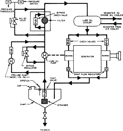
The generator lube oil system (fig. 3-28) is
condensation of moisture when the generator is
independent of the gas turbine/reduction gear
secured or on standby. Four 120-volt, 250-watt,
lube oil system. The generator lube oil system uses
tubular, finned heaters are mounted crosswise
2190 TEP mineral oil. It force-feeds the two
under the stator. They are spaced to distribute
bearings with a flow of 3 gpm at 12 to 15 psig
heat along the length of the stator. A heater
pressure. Oil is taken from the sump tank in the
control switch with an indicator lamp is mounted
GTGS base by a pump mounted on the PMA
on the control section of the SWBD. An interlock
shaft. The oil is passed through a 25-micron filter
on the generator circuit breaker automatically
and the base-mounted cooler before reaching the
disconnects the space heaters when the breaker
sleeve bearings. Gravity flow through sight flow
is closed.
indicators return the oil to the sump.
Figure 3-28.--Generator lube oil system.
3-40