
4. Permanent magnet alternator (PMA),
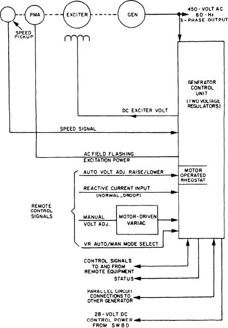
Model 139 Voltage Regulation
mounted on the generator
The major components of the model 139
5. Auto voltage control RAISE/LOWER
voltage regulator (fig. 3-31) consist of the
switch, mounted in associated SWBD
following:
6. Motor-driven variac for manual voltage
adjustment, mounted in the associated
1. Two voltage regulator assemblies (normal
SWBD
and standby), mounted in the GCU
enclosure
7. Mode select
2. Motor-operated rheostat for auto voltage
The GCU provides brushless exciter field
regulation, mounted in the GCU enclosure
3. Brushless exciter assembly, mounted on the
excitation and voltage control in the automatic
control modes.
Figure 3-31 .--Model 139 voltage regulator functional diagram.
3-44