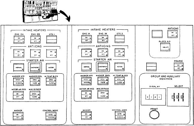
Figure 5-12.--Bleed air control panel.
orders to knots (speed), shaft rpm, and pitch
for ENG 2A, ENG 2B, and GTG 1. Five of these
settings.
control indicators control the masker system
valves and the motor air regulator valve. The last
two of the control indicators are for the
BLEED AIR CONTROL PANEL
automatic/manual operation of the masker air
This panel is shown in figure 5-12. It is divided
system valves and to select their control mode.
into three sections (two of which are identical
Under the heading INTAKE HEATERS are
except for labeling). This panel has the control
the manual control indicators (ON/OFF) for the
intake heaters of the respective engines. Under the
push-button indicators and valve status indicators
for the automatic/manual controls related to the
heading ANTIICING are the manual control
indicators (ON/OFF) for the antiicing valves of
bleed air system for each engine room. It also has
five push-button control indicators for the masker
the respective engines. Under the heading
STARTER AIR are the control indicators used
air, a push-button control indicator for the prairie
to select the starting air mode (NORMAL,
air, and valve status indicators for the GTG3. In
EMERGENCY, or MOTOR) for the selected
addition, this panel has a thumbwheel controlled
demand digital display of various conditions that
engine. The five control indicators for the
exist within the control system along with a print
masker system are for manual control of the
masker system valves when the control indicator
push button for printing thumbwheel selected
under the heading CONTROL MODE is in the
information.
MANUAL position. When this control indicator
Port and Starboard Engine Room Sections
is in the AUTO position, the PACC operator can
perform an automatic sequence (either ON/OFF)
The first section on the left of this panel is for
of all the masker valves by depressing the
control indicator under the heading MASKER.
the port engine room. It has 16 split-legend, push-
The second section is for the starboard engine
button control indicators. Nine of these indicators
room and has the identical control indicators
(three for each engine) control the INTAKE
mentioned in the first section. The exception
HEATERS, ANTIICING, and STARTER AIR
5-34

