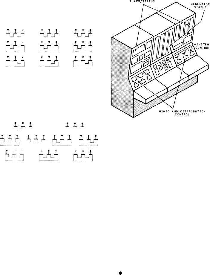
SWBDs from two generators operating in parallel.
These configurations are operator selected, or they
are the result of a failure. All electrical distribution
functions are provided with these configurations.
However, automatic recovery capability is not
available.
Emergency Configurations
An emergency configuration can occur when
two generators are inoperative, and one generator
must energize the three SWBDs. Other emergency
configurations may have all three generators
online, with all, two, or none in parallel.
Figure 8-6.--EPCC (CG- and DDG-class ships.)
Alarm/Status Indicator Section
The alarm/status indicator section is divided
into three subsections, one for each SSGTGS.
These subsections are identical. The only alarms/
indicators we will discuss are the ones that are
ELECTRIC PLANT CONTROL
added or different from the DD-class ships.
C O N S O L E (CG
CLASS SHIPS)
GENERATOR COLUMN.--The indicators
The EPCCs on the CG- and the DDG-class
in this column, labeled GEN, are the same as those
ships (fig. 8-6) are very similar to those on the DD-
on the DD consoles except the location of a few
class ships. We will only discuss the differences
of the indicators on the panel and the addition
in the consoles in this section. This console has
of the LUBO PRESS LOW indicator, which indi-
two more panels than the DD consoles. They are
cates the lube oil pressure in the generator drops
for the 60/400 Hz converters.
below the preset limit. All other indicators were
explained in the description of the DD consoles.
ALARM/STATUS PANEL
GAS TURBINE AND REDUCTION GEARS
The alarm/status panel (fig. 8-7) is the upper
COLUMN. --The indicators in this column, labeled
left panel. It contains the following sections:
GTRB, are the same as those on the DD consoles
alarm/status indicators, emergency power,
except the location of a few of the indicators on
the panel and the addition of more indicators.
generator and gas turbine lube oil meters,
synchronizing indication, SWBD emergency
BLOW-IN DOOR OPEN indicates the
power and main SWBD ground detection, alarm
blow-in doors are open.
acknowledge, and demand displays.
8-17

