
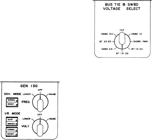
bus tie cable between the 2S and 3S SWBDs; and
mode to droop. It will cause the DROOP
SWBD 3S is for the No. 3 SWBD.
indicator to illuminate, meaning the voltage
regulator control mode is in the droop mode.
When the DROOP indicator is illuminated,
depressing the switch will output a command to
the voltage regulator to change to the normal
mode of operation.
VOLTAGE REGULATOR CONTROL
SWITCH.--This switch is located next to the
voltage regulator control mode switch/indicators
and is labeled VOLT. It is a three-position switch,
spring loaded to the center position. The center
position is labeled OFF, which is the normal
position of the switch. When the switch is turned
to the right or the RAISE position, it will cause
the voltage of the generator to increase. When the
switch is turned to the left or the LOWER
Synchro Control Section
position, it will cause the voltage of the generator
to decrease.
This section is located in the lower left-hand
corner of the panel. It has two select switches. The
top switch controls the input to the synchroscope
and synchronizing lights and the bottom switch
controls the mode of operation of the console and
the paralleling device. These switches are labeled
SYNC SELECT and OPR MODE SELECT,
respectively.
SYNC SELECT SWITCH.--This is a rotary
switch used to select between the GBs, the BTBs,
or the shore power circuit breaker. It connects the
inputs from both sides of the selected breaker to
the synchroscope and synchronizing lights, located
on the alarm/status panel. This switch also allows
the breaker selected to receive a manual close
command when it is operated in the MANUAL
PERMISSIVE mode.
BUS TIE & SWBD
The switch has an OFF position and a
VOLTAGE SELECT Section
position for each GB, each BTB, and the shore
power circuit breaker. When the switch is in the
OFF position, it will prevent all breakers from
This section is located in the upper right-hand
responding to a manual close command while in
corner of the panel. It is labeled BUS TIE &
the MANUAL PERMISSIVE mode.
SWBD VOLTAGE SELECT. It has one rotary
switch. This switch is used to select from what
OPR MODE SELECT SWITCH.--This is a
location the BUS TIE & SWBD voltmeter located
rotary switch used to select the mode of
on the generator status panel will receive its
operation of the console and the automatic
input. The top position is labeled OFF. When the
paralleling device. When the switch is turned to
switch is in this position, the meter is OFF.
the left, it is in AUTO. In this position it enables
Clockwise around the switch, SWBD 1S is the No.
the automatic recovery capability and generator
1 SWBD; SHORE PWR. is for the shore power
paralleling control device. The middle position
cables; BT 1S-2S is for the bus tie cable between
is MANUAL PERMISSIVE. In this position
the 1S and 2S SWBDs; BT 1S-3S is for the bus
it routes the close command through the
tie cable between the 1S and 3S SWBDs; SWBD
synchronizing monitor to the breaker selected by
2S is for the No. 2 SWBD; BT 2S-3S is for the
8-13