
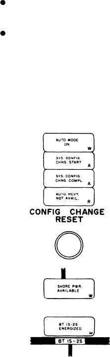
SYS. CONFIG. CHNG. COMPL. indi-
for the frequency and voltage of each generator.
cates the automatic configuration change
These indicators and controls are labeled GEN
has been completed.
1SG, GEN 2SG, and GEN 3SG from left to right.
AUTO RCVY. NOT AVAIL. indicates the
GOVERNOR MODE SWITCH/INDICA-
EPCE does not have automatic recovery
TOR.--This switch/indicator is an alternate
capability.
action push-button switch and indicator, labeled
Another indicator on this panel is the SHORE
GOV. MODE. The normal indication is with the
PWR. AVAILABLE indicator. It will illuminate
NORMAL portion illuminated. It indicates the
when shore power is connected to the ship. The
generator governor control mode is in the
last indicator is the BT 1S-2S ENERGIZED
normal operating mode. Depressing this switch
indicator. It will illuminate when the 1S or 2S
will output a command to the governor to change
SWBD is energized or shore power is applied to
the control mode to droop and the DROOP
BT 1S-2S.
portion of the indicator will illuminate, meaning
the governor control mode is in the droop mode.
When the DROOP indicator is illuminated,
depressing the switch will output a command
to the governor to change the control mode
to normal, and the NORMAL indicator will
illuminate.
FREQUENCY CONTROL SWITCH.--This
switch is located next to the governor mode
switch/indicator and is labeled FREQ. It is a
three-position switch, spring loaded to center
position. The center position is labeled OFF,
which is the normal position of the switch. When
the switch is turned to the right or the RAISE
position, it will cause the frequency of the
generator to increase. When the switch is turned
to the left or the LOWER position, it will cause
the frequency of the generator to decrease.
VOLTAGE REGULATOR MODE SWITCH/
INDICATORS. --Both of these switch/indicators
are alternate-action push-button switches and
indicators. They are labeled VR. MODE. The top
switch/indicator is AUTO/MANUAL. When
AUTO is illuminated, it indicates the generator
voltage regulator control mode is in the automatic
operating mode. Depressing this switch will
output a command to change the voltage regulator
SYSTEM CONTROL PANEL
control mode to manual. It will cause the
MANUAL indicator to illuminate, meaning
The system control panel is the lower right
the voltage regulator control mode is in the
panel (fig. 8-5). It contains the following sections:
manual mode. When the MANUAL indicator is
generators, bus tie and SWBD voltage select,
illuminated, depressing the switch will output a
synchronizing select and console mode control,
command to the voltage regulator to change to
system frequency and voltage control, power,
the automatic operating mode.
malfunction, logic self-test, test, and auto
The bottom switch/indicator is NORMAL/
paralleling.
DROOP. When the NORMAL indicator is
illuminated, it indicates the generator voltage
Generators Section
regulator control mode is in the normal mode of
This section has the indicators and controls
operation. Depressing this switch will output a
for the governor and voltage regulator mode and
command to change the voltage regulator control
8-11