
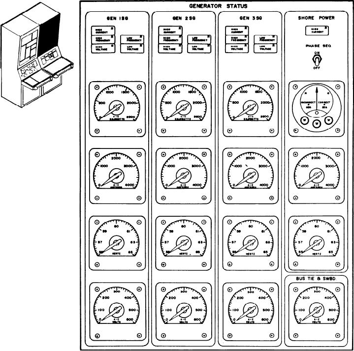
Figure 8-3.--Generator status panel.
position, it disconnects the power from the
SHORE POWER Section
PHASE SEQ meter. With the switch in the ON
or up position, it connects the power to the
This section contains one indicator, one
PHASE SEQ. meter. Below this switch is the
switch, and three meters. Starting at the top,
PHASE SEQ. meter. It is operative when the
the first item is an alarm indicator for HIGH
PHASE SEQ. switch is ON. The PHASE SEQ.
CURRENT. It will illuminate when the current
meter indicates that the phase sequence of the
on the shore power exceeds the preset limit.
shore power is incorrect or correct and that all
Below this indicator is the PHASE SEQ.
three phases are present. The next meter is the
toggle switch. When it is in the OFF or down
8-7