
that is addressed by the thumbwheel switch just
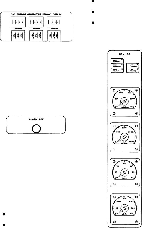
HIGH VOLTAGE indicates the voltage
below it.
exceeds the preset limit.
LOW FREQUENCY indicates the fre-
quency has dropped below the preset limit.
LOW VOLTAGE indicates the voltage has
dropped below the preset limit.
METERS.--The four meters in this section
are the KILOWATTS, AMPERES, HERTZ, and
VOLTS meters.
Alarm Acknowledge
The ALARM ACK push-button switch, when
depressed after an alarm has been received, will
silence the audible alarm and change the flashing
alarm indicator to a steady light. The following
indicator lights will continue to flash even after
the ALARM ACK switch has been depressed:
EMERGENCY POWER for the SWBDs, BAT-
TERY CHARGING, EMERGENCY POWER
for ENG RM NO. 1 and ENG RM NO. 2 (located
on this panel), and the EMERGENCY indicator
in the POWER section located on the system
control panel (discussed later in this DD-class ship
section).
GENERATOR STATUS PANEL
The GENERATOR STATUS panel is the
upper right panel (fig. 8-3). It has three sections,
one with meters and indicators for continuous
monitoring of each generator, a shore power
section, and a bus tie and SWBD section.
Generators Section
This section has three subsections, one for
each generator. The subsections are labeled GEN
1SG, GEN 2SG, and GEN 3SG. Since all these
subsections are identical, we will describe only
one.
ALARM INDICATORS.--The alarms/indi-
cators for the generator are as follows:
HIGH CURRENT indicates the current
exceeds the preset limit.
HIGH FREQUENCY indicates the fre-
quency exceeds the preset limit.
8-6