
MAIN SWITCHBOARD GROUND
operator or the ship's electric plant circuitry. A
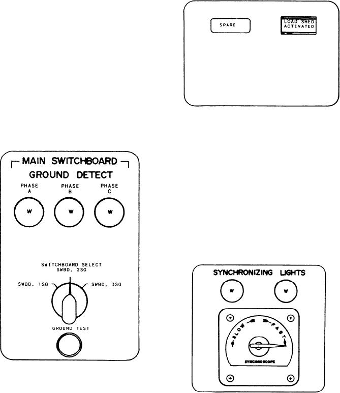
SPARE indicator is located to the left of the load
DETECT Section
shed activated switch/indicator.
This section has three indicator lights across
the top, PHASE A, PHASE B, and PHASE C.
These indicators are normally of equal brilliancy.
Below the indicator lights is the SWITCHBOARD
SELECT rotary switch. It selects the SWBD
that is being checked. At the bottom of the
section is the GROUND TEST push-button
switch. When it is depressed, it connects
the selected SWBD to the indicator lights.
A grounded condition is indicated by one
of the lights going out and the other two
lights glowing brighter. The light that goes out
is the phase that is grounded.
SYNCHRONIZING LIGHTS Section
This section contains two indicator lights and
a synchroscope meter. The SYNCHRONIZING
LIGHTS will be dark when the generators are in
phase. The brilliancy of the lights will vary
according to differences in the phases. On the
SYNCHROSCOPE, the direction of rotation of
the synchroscope pointer indicates that the
or SLOW with respect to the on-line generator.
The speed of rotation is an indication of the
amount of difference in the frequency. When the
pointer is at the 12 o'clock position, the generators
are in phase with each other.
Load Shedding Switch/Indicator
GAS TURBINE GENERATORS
DEMAND DISPLAY Section
The LOAD SHED ACTIVATED switch/
indicator, when depressed, will output a command
This section contains three sets of displays
to trip the load shedding breakers. The illumina-
and thumbwheel switches. The upper portion
tion of the indicator will result when the load
is the display and it will display the parameter
shedding breakers are opened. This may be by the
8-5