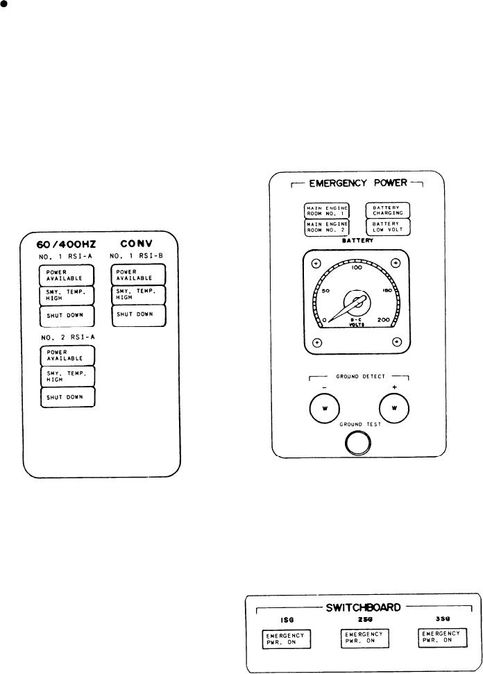
output by the UPS battery bank is below the
FUEL LEVEL HIGH indicates the fuel
preset limit. Below the indicators is the D-C
level in the tank has exceeded the high level
VOLTS meter. It indicates the output voltage of
limit.
the UPS battery bank. Located at the bottom is
the GROUND DETECT section. It has two
indicators that should be of equal brilliance. The
60/400HZ CONV Section
left indicator is for the negative lead of the UPS
circuitry. The right indicator is for the positive
The ship has three 60/400-Hz converters. This
lead of the UPS circuitry. The GROUND TEST
section has a set of identical indicators for
push-button switch is located below the indicators.
each converter. The top indicator is POWER
When you depress the switch, a dimming or
AVAILABLE, which illuminates when the
extinguishing of an indicator indicates a ground
converter is online. The middle indicator is SMY.
on that side of the circuitry.
TEMP. HIGH, which illuminates when the
temperature in the converter exceeds the preset
limit. The bottom indicator is SHUT DOWN,
which illuminates when the converter is or has
been secured.
SWITCHBOARD Section
This section has three indicators, one for each
EMERGENCY POWER Section
SWBD. Each indicator, EMERGENCY PWR.
ON, will illuminate when its related SWBD's
This section has four indicators, one meter,
power supply fails. When this condition occurs,
and two ground detect indicators with a switch.
power is supplied to the SWBD by a set of its own
The top left indicator is labeled MAIN ENGINE
24-volt dc emergency batteries.
ROOM NO. 1. It will illuminate when the ship
control system in engine room No. 1 is operating
on the UPS system. The bottom left indicator,
MAIN ENGINE ROOM NO. 2, functions the
same but is for the No. 2 engine room. The top
right indicator is labeled BATTERY CHARGING.
It will illuminate when the UPS battery bank is
on charge. The bottom right indicator, BATTERY
LOW VOLT, illuminates when the voltage
8-4

