
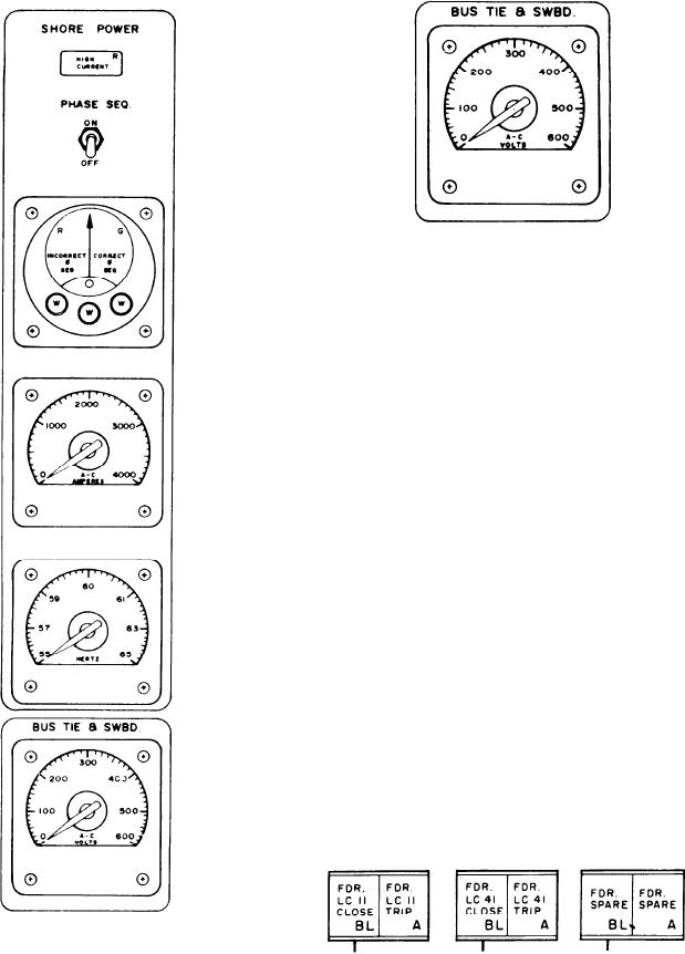
AMPERES meter. The last meter in this section
SWBD VOLTAGE SELECT switch located on
is the HERTZ meter.
the system control panel.
MIMIC PANEL
The MIMIC panel is the lower left panel (fig.
8-4). It contains a mimic bus depicting the physical
arrangement of the SWBD and bus ties. The panel
has the controls for the following circuit breakers:
generators, bus ties, load centers, and shore
power. It also has the manual start and stop
controls for the SSGTGSs and the plant control
indicators.
Circuit Breaker Switches/Indicators
All circuit breaker switches/indicators on
this panel are alternate action push-button
switches and indicators. Across the top of the
panel are the switches/indicators for the load
centers. When the FDR. LC11 CLOSE indicator
is illuminated, it indicates the breaker is
closed and feeding power to the load center.
When the FDR. LC11 TRIP switch is depressed,
it will cause the breaker to trip and the FDR. LC11
TRIP indicator will illuminate, indicating the
breaker is tripped and no power is being fed to
the load center. When the FDR. LC11 TRIP
indicator is illuminated and the FDR. LC11
CLOSE switch is depressed, it will cause the
breaker to close and feed power to the load center.
The other indicators are for different load centers
and some spares are provided.
BUS TIE & SWBD Section
The next circuit breaker switches below
This section has a VOLTS meter. The input
to this meter is controlled by the BUS TIE &
the circuit breakers/indicators for the load
8-8