
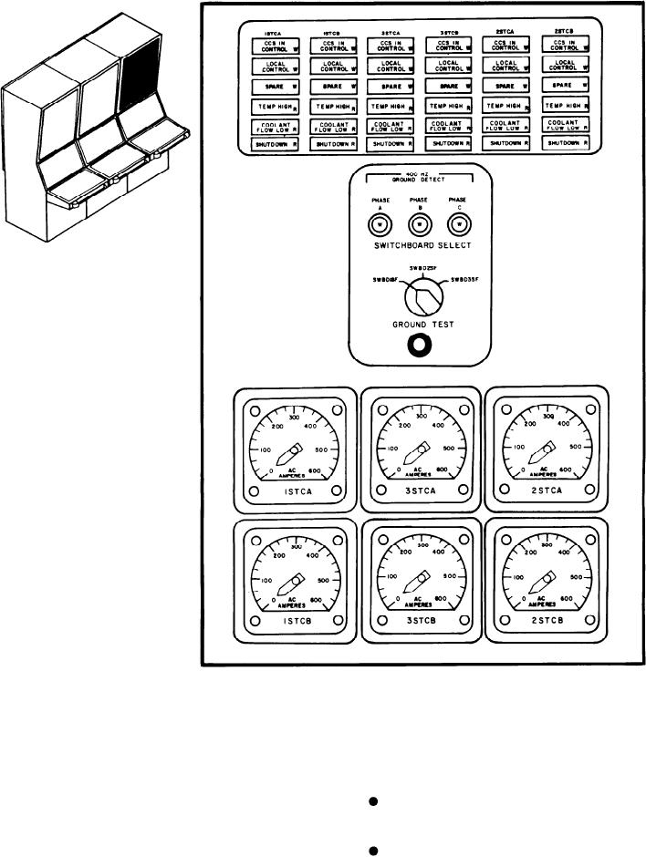
Figure 8-8.--400-Hz alarm/status panel.
right 1STCA, 1STCB, 3STCA, 3STCB, 2STCA,
ships. This panel (fig. 8-8) is divided into
and 2STCB. The indicators from top to bottom
three sections, the alarm/status indicator, ground
are as follows:
detection, and meter sections.
CCS IN CONTROL indicates the control
400-Hz Alarm/Status Indicator Section
of the converter is at the EPCC.
This section has six columns of indicators, one
LOCAL CONTROL indicates the control
for each 400-Hz converter. All the columns are
of the converter is at the converter.
identical. The columns are labeled from left to
8-20