
console. It has the TEST section with a control
and 2STCB. At the top of the section is a
knob for the ALARM VOLUME. It is located
switch/indicator that is an alternate action push-
under the HORN and BELL test switches. The
button switch/indicator. The switch/indicator is
labeled 400 HZ at the left of the switch/indicator.
alarm siren has been changed to a bell. The
SELECT switch has two added positions for the
The switch/indicator is labeled CLOSE/TRIP.
two 400-Hz panels.
When the CLOSE portion is illuminated, it
indicates the breaker is closed and feeding power
to the SWBD. When the TRIP switch is depressed, it
400-HZ MIMIC PANEL
causes the breaker to trip and the TRIP indicator
will illuminate. When the TRIP indicator is
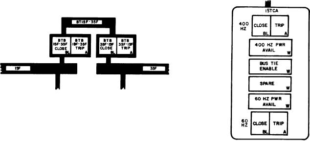
The 400-Hz MIMIC panel (fig. 8-11) is the
illuminated and the CLOSE switch is depressed,
lower right-hand panel. It has a mimic drawing
the breaker will close.
of the ship's 400-Hz system at the top of the panel.
The bottom of the panel contains controls and
Next is the 400 HZ PWR AVAIL indi-
indicators to operate the converters.
cator. When it is illuminated, the converter
is operating. BUS TIE ENABLE is the next
indicator. When it is illuminated, it means
Mimic Section
close/trip power is available to the breaker.
A SPARE indicator is located below the BUS
TIE ENABLE indicator. Below the SPARE
The mimic section contains a mimic bus
indicator is the 60 HZ PWR AVAIL indicator.
depicting the physical arrangement of the SWBD
and bus ties. This section of the panel has
When it is illuminated, 60 Hz power is available
controls/indicators for the BTBs. The BTB
to the converter.
switch/indicators are alternate action push-button
switches and indicators. The first number in the
At the bottom of this section is a switch/
legend on the indicator is the SWBD the breaker
indicator that is an alternate action push-
is located on. The second number is the SWBD
button switch/indicator. The switch/indicator
the breaker connects.
is labeled 60 HZ at the left of the switch/
indicator. The switch/indicator is labeled
When the BTB 1SF-3SF CLOSE indicator is
CLOSE/TRIP. When the CLOSE portion is
illuminated, it indicates the breaker is closed
illuminated, it indicates the breaker is closed
between the 1SF and 3SF SWBDs. Depressing the
and feeding power to the converter. Depressing
BTB 1SF-3SF TRIP indicator will cause the
the TRIP switch will cause the breaker to
breaker to trip (open) and the BTB 1SF-3SF TRIP
trip and the TRIP indicator will illuminate.
indicator will illuminate. When the BTB 1SF-3SF
When the TRIP indicator is illuminated and
TRIP indicator is illuminated, you can close the
the CLOSE switch is depressed, the breaker
breaker by depressing the BTB 1SF-3SF CLOSE
will close.
switch.
Converter Control Section
This section contains six identical subsections.
The subsections are labeled from left to
right 1STCA, 1STCB, 3STCA, 3STCB, 2STCA,
8-25