
SYNCHRONIZATION Section
PARALLELING Section
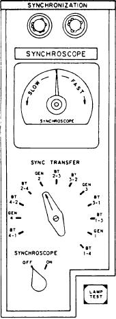
This section contains two indicator lights, a
This section is labeled PARALLELING but
SYNCHROSCOPE meter, a SYNC TRANSFER
is sometimes referred to as the APD section. It
switch, and an ON/OFF switch.
has four identical subsections, one for each
The indicator lights will be dark when the
generator.
generators are in phase. The brilliancy of the lights
will vary according to differences in the phases.
The top indicator is labeled APD POWER
The SYNCHROSCOPE meter shows the
ON. When it is illuminated, the APD has power
direction and speed of rotation. The direction of
applied to it.
rotation of the synchroscope pointer indicates that
the frequency of the on-coming generator is FAST
The switch below the APD POWER ON indi-
or SLOW with respect to the on-line generator.
cator is labeled GENERATOR 4 (1, 2, or 3). It
The speed of rotation is an indication of the
is a three-position rotary switch used to select the
amount of difference in the frequency. When the
breaker on the No. 4 SWBD that the APD will
pointer is at the 12 o'clock position, the generators
control. The left position is labeled BT 4-1. When
are in phase with each other.
the switch is in this position, the APD is connected
The SYNC TRANSFER switch is a rotary
to the BT that connects the No. 4 and No. 1
switch used to select between the generator CBs
SWBDs. The middle position is labeled BUS. This
or the bus tie (BT) circuit breakers. It connects
position is for the generator CB. The right
the inputs from both sides of the selected breaker
position is labeled BT 4-2. It is for the BT that
to the synchroscope and lights. The SYNCHRO-
connects the No. 4 and No. 2 SWBDs.
SCOPE ON/OFF switch is used to turn the
synchroscope and lights on and off.
The next indicator down is labeled APD TEST
The LAMP TEST push-button switch is
PASSED. This indicator will illuminate at the
located on the lower right corner. It is used to test
time the permissives have been met to close the
the indicator lights on the A-2 panel only.
circuit breaker.
The bottom switch is labeled MODE. It is a
four-position rotary switch. The MODE switch
is used to select the mode of operation of the
APD. The left position is labeled BYPASS. This
position is used only when the APD is inoperative,
when APD permissives cannot be met, or when
manual paralleling by the operator is required.
This position bypasses the APD's CB closing
permissives. The MODE selector switch is spring
returned from BYPASS to AUTO. The operator
must hold it in the BYPASS position while the
CB control switch (not shown) is turned to the
CLOSE position. This is done when the two
points in the electric plant to be paralleled are
synchronized. Also, the operator has to use the
APD BYPASS position to close a CB to a dead
bus and to the last breaker in a ring bus. The
straight up position is labeled AUTO. In this
position the APD automatically adjusts the speed
of an oncoming generator to synchronize it with
an energized portion of the electric system. It then
provides a signal to close the designated CB. The
next position is labeled PERM. In this position
the APD acts as a safety interlock. It prevents the
closing of the designated CB unless the required
permissives are met. When operated in this mode,
the APD functions as a monitoring device, not
8-30