
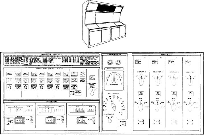
Figure 8-14.--SCS/synchronization/paralleling/parameters panel (A-2).
low-level alarms. The panel also has push-button
shows the command being sent to the valve from
switches to control the suction valve on each tank
the console.
and an indicator to show the position of each
The LAMP TEST push-button switch is
valve.
located on the lower right corner. It is used to test
Tanks 5-201-1-F and 5-201-3-F are for No. 1
the indicator lights on the A-l panel only.
SSDG, tanks 3-240-1-F and 3-240-2-F are for
No. 2 and No. 3 SSDGs, and tanks 3-292-4-F and
SUPERVISORY CONTROL STATUS/
3-292-6-F are for No. 4 SSDG. All tanks have the
SYNCHRONIZATION/PARALLELING/
same layout, a meter with indicators at the top,
PARAMETERS PANEL (A-2)
the bottom, and to the right of the meter. The
indicators are the HIGH LEVEL and the LOW
This panel (A-2) (fig. 8-14) is the upper middle
LEVEL alarm indicators, respectfully. The alarm
panel. It has the parameter addresses, SCS,
indicators also have a 3-digit number on the
synchronization, paralleling, and parameters
indicator. This number is the DDI address for that
sections.
parameter. (When these 3-digit number sequences
are next to an indicator/alarm, they will always
SUPERVISORY CONTROL
indicate a DDI address on this class ship). The
STATUS Section
two indicators in the middle and to the right of
the meter are for the suction valve of the
The SCS section is divided into six subsections.
respective tank. The top indicator is the position
Four are identical, one for each SSDG; the other
indicator, and the bottom indicator is a push-
two are for the overall plant and SCS control
button switch that is used to control the valve.
switch.
Both indicators are labeled SUCTION V OPEN/
The SSDG subsections each contain six
CLOSED. The top indicator shows the actual
indicators. The indicator circuitry is in operation
only when the SUPERVISORY CONTROL
position of the valve. The bottom indicator
8-28