
vital power feeder circuit breaker status panel
ELECTRIC PLANT CONTROL
(A-3), SSDG panels (A-4 and A-7), SSDG output
CONSOLE (FFG-CLASS SHIPS)
and distribution panels (A-5 and A-8), system
output monitor/ground status test/generator 4
The EPCC on the FFG-class ships contains the
voltage control panel (A-6), and shore power/
controls and indicators used to remotely operate
generators panel (A-9). The lower portion of the
and monitor the SSDGs and power distribution
EPCC contains three fuse panels.
system.
The EPCC (fig. 8-12) is subdivided into nine
ENGINE FUEL SYSTEMS PANEL (A-1)
panels and each panel is dedicated to a particular
type of control and monitoring. The panels are the
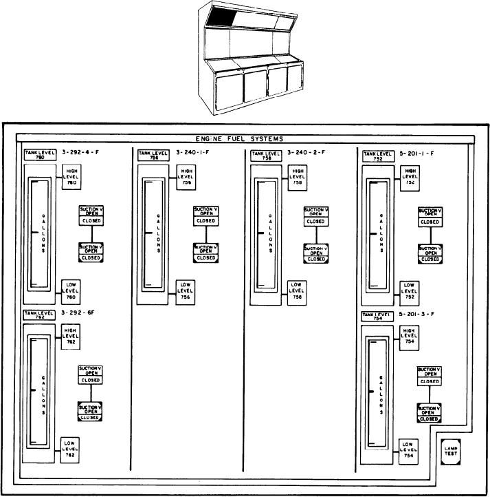
The ENGINE FUEL SYSTEMS panel (A-1)
engine fuel systems panel (A-l), supervisory con-
(fig. 8-13) is the upper left panel. It contains a
trol status(SCS)/parameters/synchronization/par-
meter for each fuel tank with associated high- and
alleling panel (A-2), console power status/console
Figure 8-13.--Engine fuel systems panel (A-l).
8-27