
The bottom two indicators illuminate to
A section (M), labeled AUDIBLE
display the status of the GTE clutch. These
ALARMS, has two push-button indicators
indicators are labeled CLUTCH ENGAGED and
and a rotary switch. The first push-button
CLUTCH DISENGAGED.
indicator, labeled SIREN TEST, is
depressed by the operator to test the alarm
The third push-button indicator, labeled
siren. T h e rotary switch, labeled
FUEL PURGE VALVE OPEN, operates the
VOLUME, is actually a rheostat used to
GTE's fuel purge valve. When this push button
adjust the volume of the audible alarms.
is depressed, it opens the fuel purge valve to allow
The second push-button indicator, labeled
about 3 gallons of cold fuel to drain from the GTE
HORN TEST, is depressed by the operator
system. In this way, cold fuel is drained from the
to test the alarm horn.
GTE before starting. The fuel purge valve is
operated only when motoring the GTE.
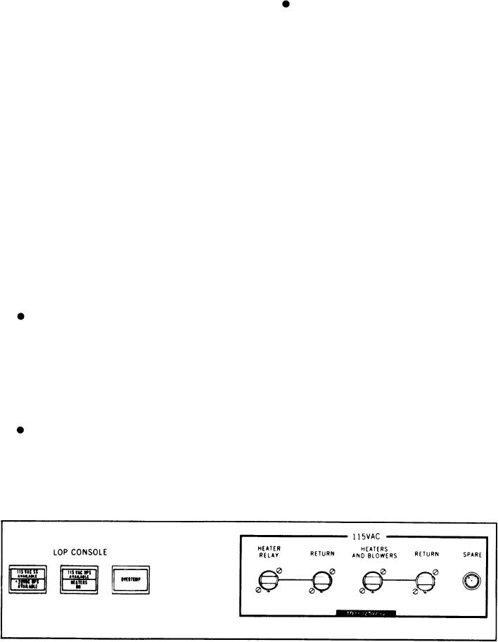
LOP STATUS PANEL
With the exceptions noted in the previous
sections (two edgewise meters, one alarm
The LOP status panel (fig. 6-15) is located to
indicator, and the LAMP TEST push button), all
the right of the 1A GTE top panel. It contains
of the indicators, push buttons, edgewise meters,
three illuminated indicators for the LOP power
supplies and five fuse holders for the 115 volts
and rotary switches described on the LOP top
panel are identical on both the engine 1A and
ac for the console heaters and blowers.
engine 1B panels. The following indicators, push
buttons, and rotary switch are located on the
The first indicator is a split-legend indicator,
engine 1A panel and are NOT on the engine 1B
labeled 115 VAC SS AVAILABLE/+28 VDC
panel.
UPS AVAILABLE. It displays the status of
115-volt ac ship's service power and 28-volt dc
A push-button indicator (K), labeled
power. These indicators will illuminate when
ALARM ACK, is located on the engine 1A
each source of power is available. The second
panel at the position shown. It is a
indicator is also a split-legend type, labeled
momentary-contact push button used by
115 VAC UPS AVAILABLE/HEATERS ON.
the operator to acknowledge an alarm.
It illuminates to indicate 115-volt ac UPS is
When it is depressed, it will cause the
available and when the console heaters are on.
flashing alarm indicator to illuminate in
The third indicator, labeled OVERTEMP,
a steady state and silence the alarm.
illuminates and sounds an alarm to indicate
console overtemperature.
A split-type indicator (L), labeled EN-
GAGED/DISENGAGED, illuminates to
The 115 VAC fuse section contains the fuses
for the power and return for the heater relay,
indicate the status of the MRG turning
power and return for the heaters and blowers, and
gear. The turning gear must be engaged
and disengaged manually at the MRG.
a spare fuse holder.
Figure 6-15.--LOP status panel.
6-35