assembly for each side of the craft consists of a 2-stage,
and closed from the engineer station. These switches do
free-power turbine and a combination axial/centrifugal
not use power from the CSEP.
compressor driven by a two-step, axial-flow turbine.
INDICATORS. The following indicators are
(Compare figs. 6-1 and 6-13.) Each of these assemblies
provided to inform the operator of the status of the
is the power source that drives the lift fans, propellers,
cushion vanes:
and forward and aft gearboxes for that side of the craft.
The lift fans and propellers are interconnected through
Port and starboard cushion vane position (bar
the drive train by offset and engine gearboxes. There is
graph)
a manual clutch provided on each power train to allow
Port and starboard cushion vane digital position
the forward engine to be disconnected from the aft
engine.
The operator uses this information to achieve the most
effective movement of the craft.
Engine Start/Stop Switches
LYCOMING TF40B ENGINE
The function of the TF40B engine start/stop
CONTROL SYSTEM
switches is to allow the operator to start and stop the
engines from the control station. Each engine has a
The TF40B engine control system provides the
START/STOP switch and an OFF/IDLE/RUN master
operator with controls and indicators to operate the
switch. The START/STOP switches send signals to the
engines and to move the craft effectively and safely. The
engine sequencing units, then to the respective engine
engine control system consists of the following five
control box, to carry out the ordered function.
control and indicator panels:
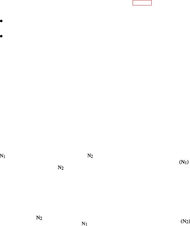
1. N1
Engine Balancing Control Potentiometers
2. N2
The function of the engine balancing control
3. Engine balancing
potentiometers is to control the power output of each
engine to make sure the engines are balanced.
4. Engine instrument
5. Engine start
Gas Producer Controls
The
unit is the gas producer control unit. The
unit
is the power producer control unit. The engine balancing
The gas producer controls
are used by the
unit to balance the
control unit is combined with the
engineer to set the speed of the engines. These controls
power outputs of the four TF40B engines. The engine
are located in the engineer control station. The primary
instrument panel provides an analog indication of
function of these controls is to allow the operator to
engine operating conditions. The engine start panel
control the speed of the gas turbine engines and move
gives the engineer or craft operator control of the engine
the craft.
start and shutdown cycles.
Power Producer Controls
The controls for the TF40B engine control system
are powered from two dc power panels and by signals
Like the gas producer controls, the primary function
from the CSEP. The
and engine balance control
of the pwer producer controls
is to allow the
signals are combined through the CSEP. The
control
operator to control the speed of the engines. When the
signals are supplied with a positive-to-negative control
operator uses the power producer controls, a signal goes
voltage range from the CSEP.
to the CSEP and the correct engine control boxes to
Now that you have read about the control and
control that engine's speed.
indicator panels, let's take a look at the gas turbine
engines and their associated controls.
Automatic Shutdown Normal/Override Switch
Gas Turbine Engines
The automatic shutdown, normal/override switch
allows the craft operator to inhibit all automatic
As stated earlier, the four direct-drive, high-speed
shutdown features of the TF40B except an overspeed
TF40B gas turbine engines are located in pairs on the
condition. This switch allows the operator to control the
port and starboard sides of the craft. The two-engine
engines under battle conditions. This component was

