
double-discharge centrifugal fans, four air inlets, four
discharge ducts, and eight flow control vanes. Each
air inlet is protected by a foreign object damage
(FOD) screen. Each fan is installed on an individual
shaft. These shafts are connected to each other and
then to the forward offset gearbox by flexible
couplings. Each fan has one discharge volute directed
upward to the bow thruster assembly.
Solenoid-Operated Valves
Four 4-way, 3-position solenoid-operated valves
allow the engineer to control the cushion vanes.
Momentary push-button switches located on the C&C
keyboard allow the operator to control these valves.
(See fig. 6-14.) Each valve has an A and a B solenoid.
Solenoid A energizes when the VANE CLOSE push
button is depressed. Solenoid B energizes when the
VANE OPEN push button is depressed. Depressing
the push button allows hydraulic pressure to be
applied to the actuator, which causes the cushion
vane to operate. These valves have manual overrides
in case an emergency occurs.
Cushion Vanes
The function of the cushion vanes is to allow the
engineer to control the amount of airflow going to the
cushion vanes and bow thrusters. Four switches on
the C&C keyboard allow the engineer to control these
vanes. The 16 vanes in the system are adjustable
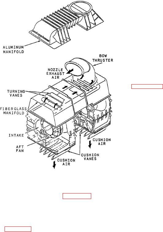
Figure 6-12.--Lift fans and cushion vanes
through any degree of rotation ordered by the
assembly.
operator.
The structure of the lift fans and associated vane
OPERATING MECHANISM. The purpose of
cushion assembly is shown in figure 6-12. The main
the cushion vanes operating mechanism is to open
components of this system are four double-entry
and close the cushion vanes. Each mechanism
centrifugal fans. A rectangular box structure
consists of four bellcrank assemblies, four torque
containing two lift fans is located on each side of the
tubes, and one actuator. Hydraulic pressure supplied
craft. The fans are driven by the TF40B gas turbine
to the actuator, through the 4-way, 3-position,
engines through right-angle gearboxes, as illustrated
solenoid-operated valve, causes the bellcranks to turn
in figure 6-13. The lift fan control system uses the
and operate the cushion vanes.
output of the TF40B engines, throughshafts, and
reduction gears to turn the fans that provide air to
EMERGENCY CUSHION DUMP SWITCH.
the cushion and the bow thrusters.
The emergency cushion dump switch allows the
operator to dump the craft air cushion during an
Sixty percent of the air goes to the cushion and
emergency stop. When the switch is depressed, all
forty percent goes to the bow thrusters. The air going
four 4-way, 3-position, solenoid-operated valves are
to the cushion can be increased or decreased by
energized to supply adequate hydraulic pressure to
opening or closing the four sets of cushion vanes.
the hydraulic actuators. The actuator movement
Let's take a look at the components of this system and
closes all four cushion vanes and takes the craft off
how they work.
cushion,
Lift Fans
SELECTOR SWITCHES. Four momentary
As described earlier, there are two identical lift
contact push-button selector switches located on the
fan assemblies port and starboard. Each side has two
C&C keyboard allow the cushion vanes to be opened