
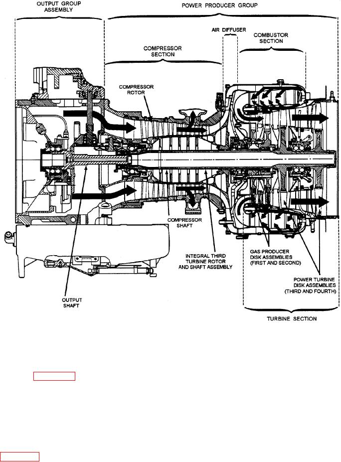
Figure 6-3.-Operation and primary airflow of TF40B gas turbine engine (LCAC).
compressor shaft, is splined to the power output shaft
Components and Assemblies
assembly. The power output shaft assembly is located
at the forward end of the engine. Its speed is equal to
As you study figure 6-2, notice how the TF40B is
power turbine speed. Externally, the power output
basically composed of two major sections: (1) the
group assembly provides mounting pads for several
output group assembly and (2) the power producer
accessories and components required for engine
group. The power producer group includes the gas
operation.
producer module and the combustor and the power
turbine assembly. The output group assembly
Notice how the two major sections of the TF40B
includes the accessory gearbox module, inlet housing
are structurally interdependent. Working together as
module, and sump module. The power producer group
an operating unit, they provide an annular flow path
provides a reverse annular flow path for air and hot
for the air or hot gases, support internal rotating
gases. (See fig. 6-3.) The compressor rotor assembly is
systems, and provide external attaching capabilities
directly connected to the first and second gas
for components and accessories required for engine
producer disk assemblies. The fourth turbine rotor
operation. An important advantage of this design is
disk assembly is directly connected to the power
that it allows for the removal and installation of
turbine integral third turbine wheel disk shaft
engine modules. This
assembly. This assembly, which runs inside of the