
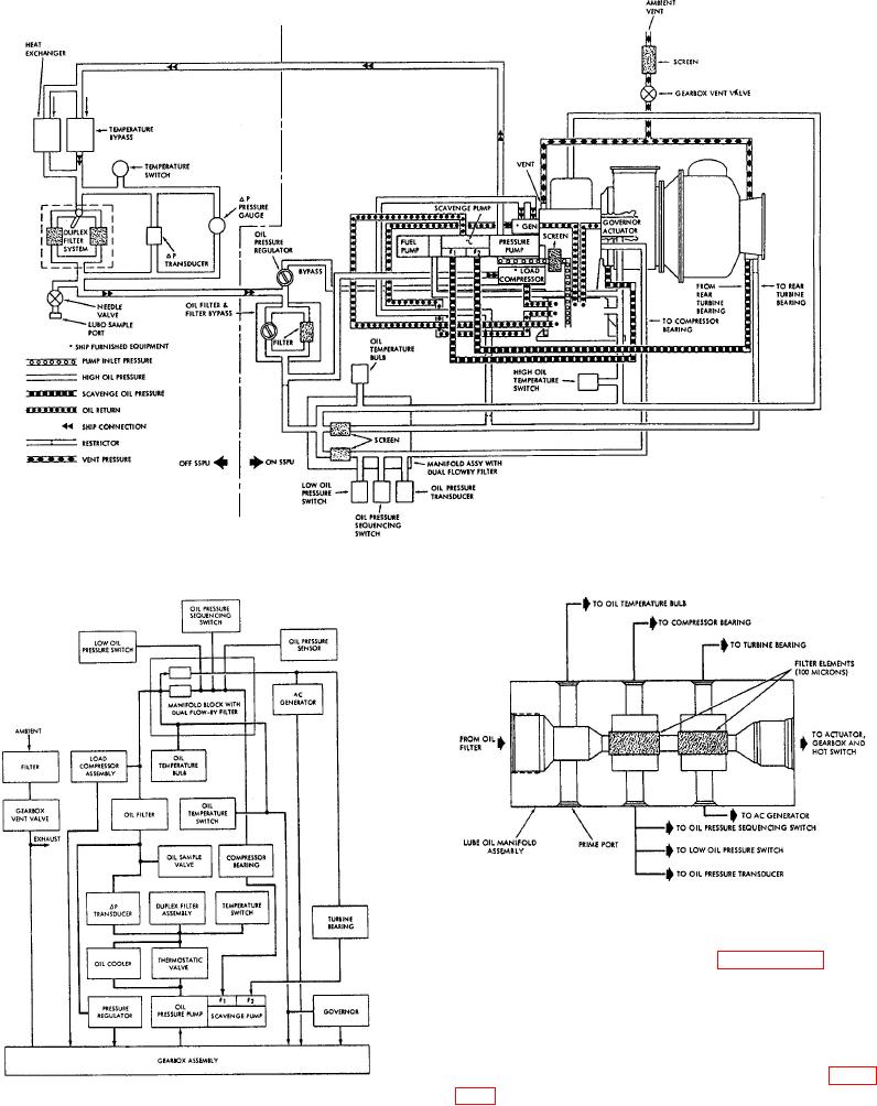
Figure 7-14.-Garrett lubrication system.
Figure 7-16.Garret lube oil manifold assembly
showing oil flow.
These components are shown in figures 7-14 through
7-17. Refer to these figures as we discuss the Garrett
lube oil system's components and their functions.
Oil Flow
First, locate the oil pump and suction tube in figure
7-14. The oil pump uses the suction tube to pickup the
Figure 7-15.Garrett lubrication system block
oil. A screen in the suction tube filters the oil before it
diagram.
enters the pump. From the pump, the oil flows through