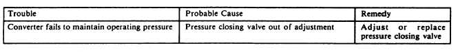
Table 12-23.-Troubkshooting (Flow Test)
8. Remove the fill valve adapter you installed
in step 1.
FLOW TEST
To perform the flow test, proceed as follows:
1. Secure the converter in the rack on the test
stand countertop.
2. Using the Test Stand Hose Assembly, P/N
59A120-B5-12,
connect
the
test
stand
FLOWMETER CONNECTION, NIP-4, to the
CONVERTER SUPPLY OUTLET CONNEC-
TION, NIP-5.
3. Using the Test Stand Hose Assembly, P/N
59A120-B5-47, connect the test stand SUPPLY
TO CONVERTER CONNECTION, NIP-6, to
the converter quick-disconnect coupling.
4. Place the test stand FLOWMETER
SELECTOR valve V-1 in the 0-150 1pm position.
Open the TEST PRESSURE GAUGE BUILDUP
AND FLOW valve V-10. You should not have
a reading of over 70 psig on the test pressure gauge
PG-1. If the test pressure gauge reads over 70 psig,
vent the converter system pressure to 70 psig (refer
to NAVAIR 13-1-6.4).
5. Open the test stand CONVERTER SUP-
PLY FLOW CONTROL valve, V-9, to give a
flow of 120 1pm as indicated on the
FLOWMETER INDICATOR gauge, PG-2.
Maintain the flow for a minimum of 15 minutes.
6. While maintaining a 120 1pm flow, the
converter should maintain pressures of 55 to 90
psig as indicated on the TEST PRESSURE gauge,
PG-1. Record the high and low pressures in the
indicated blocks in section 10 of the Performance
Test Sheet.
7. If the converter supply pressure is not
within limits, locate probable cause using the
troubleshooting chart (table 12-23).
8. Continue flowing the converter until it is
completely empty of LOX. Any means of
evacuating LOX from the converter is acceptable,
provided all safety precautions are followed.
9. Disconnect the test stand hose assemblies,
which you attached in steps 2 and 3. Close all test
stand valves.
CONVERTER CHARGE
Upon completion of the bench test, the
converter is charged with gaseous oxygen to 25
to 30 psig to prevent entry of moisture and other
contaminants during shipment/storage. To charge
the converter, proceed as follows:
1. Secure the converter in the rack on the test
stand countertop, unless it is already there.
2. Using the Test Stand Hose Assembly, P/N
59A120-B547, connect the test stand BELL JAR
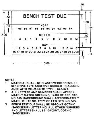
Figure 12-19.—Bench test decal.
12-32