service, and at intervals not exceeding 231 days
thereafter. This interval applies to all converters;
aircraft-installed, shop spares, and those main-
tained in a servicing pool.
The calendar inspection consists of a visual
inspection followed by a bench test. All work is
performed in a clean, dust-free and oil-free area.
Converter assemblies found to be damaged or out
of adjustment are repaired by replacing or
adjusting the discrepant part or parts. After
repair, repeat the bench test.
VISUAL INSPECTION
Visually inspect the converter assembly in
accordance with table 12-18.
Liquid oxygen converters failing the visual
inspection or bench test are repaired, if the specific
repair is authorized. SM&R maintenance is
authorized to perform repairs. Further explana-
tion is found in Naval Aviation Maintenance
Program (NAMP), OPNAV 4790.2 (series).
SERVICE LIFE
Liquid oxygen converters can remain in service
as long as they continue to function properly.
BENCH TEST
The bench test is performed using the Liquid
Oxygen Converter Test Stand P/N 59A120,
31TB1995-1 or 31TB1995-4. Refer to chapter 11
for identification of test stand controls and
indicators referenced in bench test procedures. Do
not attempt to perform any bench test without
first becoming thoroughly familiar with the test
stand. Use Performance Test Sheet (fig. 12-8)
when performing the bench test.
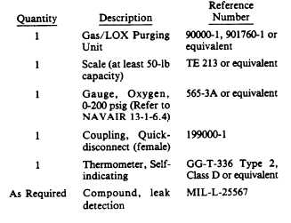
The following tools and materials are required
for this test:
In the following descriptions, the tests are ar-
ranged so they proceed from one test to the next
with
a
minimum
o f f l o w
changes.
Troubleshooting tables accompany many of the
tests.
The first step in the bench test is to find the
tare weight of the converter. Tare weight is the
weight of the complete converter assembly less the
weight of the LOX. Proceed as follows:
1. Ensure all LOX has been removed from the
converter.
2. Place the converter assembly on scales
having at least a 50-pound capacity. Record
weight in space provided on performance test
sheet.
CONVERTER ASSEMBLY PURGE
As we mentioned before, the converter should
be purged before any test. This purging is the key
to a trouble-free operating converter. Only dry,
oil-free nitrogen, Type I, Class 1, Grade A (FED
SPEC BB-N-411) is to be used for purging con-
verters. While operating purging unit, you have
to wear protective gloves. The discharge fittings
can reach temperatures that will cause severe
burns if grasped with bare hands.
Before starting to purge the unit, empty it of
LOX and allow it to warm to room temperature.
Then proceed as follows:
1. Cap the converter quick-disconnect cou-
pling assembly and attach a drain line to the
quick-disconnect coupling assembly.
2. Ensure the purge unit power switch is OFF.
Connect the purging unit electrical power cable
to a suitable electrical power source.
3. Open the N2 supply cylinder valve and the
purge unit inlet valves.
4. Turn the purge unit power switch ON, and
allow the unit to warm up approximately 10
minutes.
5. Measure the outlet temperature of the
purge unit using a thermometer, GG-T-336, Type
2, Class D or equivalent. Temperature should be
between 200 °F (93 °C) and 250°F (121 °C) prior
to connecting the purge unit to converter.
6. Connect the purging unit to the fill,
buildup, and vent valve of converter.
7. Purge the converter assembly. The
maximum inlet pressure and temperature should
be 55 psig and 250 °F, respectively. The purge time
for 10-liter LOX converters which are at ambient
temperature is from 45 to 75 minutes.
12-27