pair of cables winds onto the drum while towing the
grab. The other pair of cables is unwound from the
drum by movement of the grab. The traverse carriage
moves in proportion with the drum rotation and feed the
cables on and off the drum.
GRAB
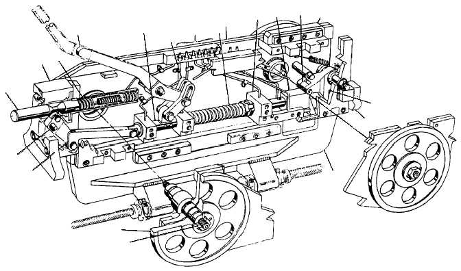
The grab (fig. 4-49) is a spring-loaded latch,
mounted on a wheel frame and installed within the
shuttle track behind the shuttle. The two retract cables
are fastened to the aft end of the grab, and the two
advance cables to the forward end. After a launch, the
grab is pulled forward the length of the shuttle track by
the drive system, and automatically latches to the
shuttle with a positive-locking device. Diagram A of
figure 4-50 shows the grab in the UNLOCKED
position, approaching the shuttle. When the grab latch
(5) comes in contact with the shuttle clevis pin (6), the
latch rotates and the latch cam follower (8) moves out
of the cam detent (7) in the lock block (9) and continues
upward until it reaches the top surface of the lock block.
The spring-loaded lock block then moves under the
cam follower, trapping the latch and locking the grab to
the shuttle clevis pin, as shown in diagram B. The grab
will not release the shuttle until both have been returned
to the BATTERY position and the grab unlocking
mechanism is actuated by the bridle tensioner. When
the bridle-tensioner piston rod moves forward, the
bridle-tensioner buffer cap (11) pushes the grab
pushrod (1) inward until the buffer cap contacts the
grab block (2). When the pushrod is pushed inward, the
lock block (9) is pulled from under the latch cam
follower and the latch is free to rotate and release the
shuttle, as shown in diagram C. When the shuttle and
bridle tensioner move away from the grab, the grab
remains in the UNLOCKED position, as shown in
diagram A. During no-load tests, the grab and shuttle
must be unlatched. The grab is manually released from
the shuttle, as shown in diagram D. A manual-release
disengaging
lever
(12)
is
placed
over
the
manual-release arm (3), which is accessible through the
track slot, lifted up and pushed forward. This motion
pulls the lock block from under the latch cam follower
and frees the latch so that the grab and shuttle can be
separated.
4-41
1
2
3
4
5
6
7
89
10
11
12
13
14
15
16
17
18
19
20
ABEf0450
1. Pushrod
2. Block
3. Spring
4. Manual-release arm
5. Slide shaft
6. Link
7. Lubrication fitting
8. Spring
9. Plate
10. Support
11. Block
12. Cam follower
13. Upper tie bracket
14. Latch
15. Buffer plate
16. Bracket
17. Shaft
18. Wheel assembly
19. Link
20. Lever
Figure 4-49.—Grab.


