the dome of the tensioner regulator and the pressure in
the hydraulic fluid side of the tensioner surge
accumulator. Valves on the panel are used for charging
and blowing down the air flask, the air side of the main
hydraulic
accumulator,
the
air
side
of
the
cable-tensioner accumulator, the dome of the tensioner
regulator, and the air side of the tensioner surge
accumulator. There is also a valve to shut off the
low-pressure-air supply. A bank of red and green
indicator lights on the panel indicates go and no-go
indication for various catapult functions.
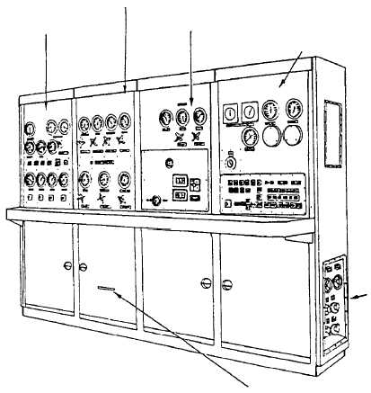
RIGHT-INTERMEDIATE-FRONT PANEL.—
The top portion of the right-intermediate-front panel
contains the pressure gauges and valves monitoring,
charging, and blowing down the nose gear launch
accumulators. The lower portion of the panel contains a
24-hour clock and the CSV setting controls.
RIGHT-FRONT PANEL.—The right-front panel
top portion contains the launch valve timer readout,
water
brake
elbow
pressure
gauges,
the
wet
accumulator pressure gauge, the main power (RC)
on/off switch and a panel with the steam fill/blowdown
valve selectors. The lower portion of this panel contains
lights and switches for operating and monitoring
catapult and wet steam accumulator components. The
lowest row of lights and switches provide emergency
operational capability at the charging panel.
Transfer Switch Enclosure
The transfer switch enclosure is located on the
lower right end of the central charging panel. The
switch enclosure contains switches that provides a
means of transferring catapult control functions for
operating in either the deckedge or central charging
panel emergency mode. The other switches provide a
means of transferring pri-fly, deck signal lights, central
control station, and the catapult interlock switch out of
the catapult control circuit.
Launch Valve Emergency Cutout Valve
The launch valve emergency cutout valve is located
on the lower left end of the central charging panel. The
emergency cutout valve provides the central charging
panel operator with a positive control to prevent the
launch valve from opening during a HANGFIRE
condition. When placed in the emergency position, the
cutout valve electrically and hydraulically shifts the
launch valve control system to the closed position.
4-49
LEFT-FRONT PANEL
LEFT-INTERMEDIATE-FRONT PANEL
RIGHT-INTERMEDIATE-FRONT PANEL
RIGHT-FRONT PANEL
TRANSFER SWITCH
ENCLOSURE-BOX
DECK SIGNAL LIGHT CONTROL
ABEf0461
Figure 4-60.—Central charging panel.