STEAM CUTOFF PRESSURE-SWITCH
INSTALLATION
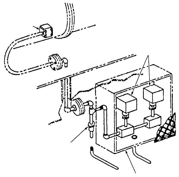
The steam cutoff switch installation (fig. 4-30)
consists of two pressure switches and associated piping
mounted in an intrusion-proof enclosure. The steam
cutoff pressure-switch installation is located at a point
in the catapult power stroke determined during the
catapult certification program. Flexible tubing connects
the steam cutoff pressure switch assembly to a port in
one of the launching engine cylinders. After the
catapult is fired, when the launching engine piston
passes the port that is connected to the cutoff switches,
steam pressure actuates each switch. This initiates the
launch complete phase of operation and the subsequent
closing of the launch valve. The pressure switches are
preset to close at an increasing pressure of
approximately 20 psi and open at decreasing pressure
of approximately 10 psi.
CATAPULT TROUGH INSTALLATION
The catapult trough installation (fig. 4-31) provides
a means of covering the catapult trough and providing a
track within which the shuttle and grab rollers ride. In
addition, it covers the launching engine components
and seals the launch valve area from fluid spills and
debris.
4-22
ADAPTER
FLANGE
DISK ORIFICE
INTRUSION-PROOF
ENCLOSURE (REF)
SWITCH
ABEf0431
Figure 4-30.—Steam cutoff pressure switches.


