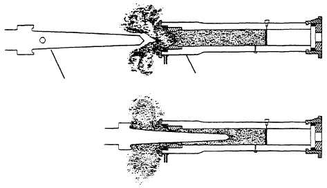
The water brakes stop the forward motion of the shuttle
and pistons at the end of the catapult power stroke. The
after end of each water-brake cylinder is supported and
aligned by the most forward section of each launching
engine cylinder, which telescopes over the after end of
the water-brake cylinder. The forward end of each
cylinder is anchored in place by an upper bracket and
lower support saddle and chock.
The open end of each cylinder holds four rings.
They are the choke ring, the annulus ring, the jet ring,
and the striker ring.
The choke ring is the innermost ring and is threaded
into the water-brake cylinder. The annulus ring has
angled holes machined in it to direct pressurized water
into the cylinder and forms a vortex (whirlpool) at the
open end of the cylinder. The jet ring is bolted to the end
of the cylinder and holds the annulus ring in place. The
striker ring, the outermost of the four rings, are
designed to absorb the impact of any metal-to- contact
between the launching engine piston assemblies and
the aft end of the water brakes.
WARNING
To prevent damage to the water brakes and
piston assembly components, a water-brake
pump must be running any time the shuttle and
piston assemblies are not fully bottomed in the
water brakes.
A vane is keyed to the end plug (see fig. 4-27). Its
purpose is to break up the vortex caused by the annulus
ring and to create a solid head of water in the cylinder,
which is maintained by the continued vortex action at
the mouth of the cylinder.
Braking action occurs at the end of the power run
when the tapered spear on the piston assembly enters
the water brake. Water in the brake is displaced by the
spear and forced out the after end of the cylinder
between the choke ring and the spear (fig. 4-28). Since
the spear is tapered, the space between the choke ring
and the spear is gradually decreased as the spear moves
into the brake cylinder. This arrangement provides a
controlled deceleration and energy absorption, which
stops the piston assembly within a distance of about 5
feet without damage to the ship's structure.
WATER-BRAKE TANK
The water-brake tank is installed below the
water-brake cylinders to supply water to and reclaim
water spillage from the water brakes during operation.
It has a minimum capacity of 3,000 gallons of fresh
water. Overflow and oil-skimming funnels and bottom
drains are provided in the tank to maintain proper water
level and to remove excess oil used in the lubrication of
the launching engine cylinders.
WATER-BRAKE PUMPS
Water is supplied to the water-brake cylinders by
two electric-motor-driven, rotary-vane-type pumps
installed in the immediate vicinity of the water-brake
tank. They are capable of producing 650 gallons of
water per minute at 80 psi. The pumps are electrically
interlocked so that if the running pump breaks down,
4-20
PISTON SPEAR
WATER BRAKE CYLINDER
ABEf0429
Figure 4-28.—Water brakes.


