set of jaws wedged into a hollow sleeve and held in
place by a threaded cap
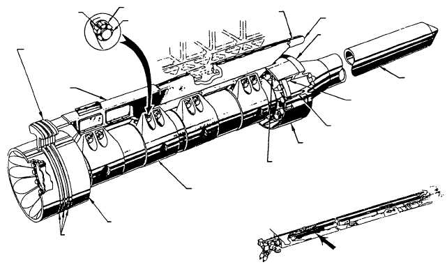
STEAM PISTON ASSEMBLY
The launching engine piston assembly (see fig.
4-25) consists of left and right hand launching pistons
and attaching parts. The launching engine pistons are
installed side by side in the launching engine cylinders
the shuttle assembly provides the connection for one
launching piston to the other along with the connection
to the aircraft. The pressurized steam in the launching
engine cylinders drives the launching engine steam
piston assemblies. They, in turn, drive the shuttle.
Component parts of each piston assembly are the steam
piston, the barrel, the connector, the strip guide, the
piston guide, and the tapered spear
The barrel serves as the chassis for the other
components of the assembly. The piston is bolted to the
aft end of the barrel; the piston rings installed on the
piston seal the space between the piston and the
cylinder wall. The cylinder cover segmented seal
assembly acts as an extension of the piston into and
through the cylinder slot. This seal assembly consists of
a housing, three upper seal segments, and six lower seal
segments. The upper seal segments press against the
cylinder covers, and the lower seal segments press
against the sides of the cylinder slot to prevent the loss
of steam pressure from behind the steam pistons as the
piston assemblies move through the cylinders during
the power stroke. The connector and the strip guide are
bolted to the top of the barrel. The connector lifts the
sealing strip off its seat to permit passage of the shuttle
assembly along the cylinder. The strip guide returns the
sealing strip to its seat after the connector passes under
it, minimizing loss of steam pressure as the piston
assembly advances through the power stroke. In
addition, the connector has interlocking "dogs," which
couple with matching "dogs" on the shuttle assembly to
effect the connection between the connectors and the
shuttle assembly.
The tapered spear and bronze piston guide are
bolted to the forward end of the barrel. The piston guide
acts as a bearing surface for the piston assembly and
keeps it centered with respect to the cylinder walls. The
tapered
spear
works
in
conjunction
with
the
water-brake cylinder assemblies to stop the piston
assemblies and shuttle at the end of the power stroke.
SHUTTLE ASSEMBLY
The shuttle assembly (see fig. 4-26) carries the
forward motion of the pistons to the aircraft by means
of a launch bar attached to the aircraft nose gear and
connected to the nose gear launch shuttle spreader. The
meshing of interlocking “dogs” of the piston assembly
connectors and the shuttle frame connect the shuttle
and the piston assemblies.
The shuttle is essentially a frame mounted on
rollers. Two pairs of rollers fitted with roller bearings
4-18
NUT
BOLT
COTTER PIN
RUBBING
STRIP
CONNECTOR
DEFLECTOR
RING
SPEAR
SUPPORT
GUIDE
BOLT
PISTON
GUIDE
STUD
BARREL
PISTON
CYLINDER
COVER SEAL
SEALING-
STRIP
GUIDE
ABEf0426
PISTON
RINGS
Figure 4-25.—Launching engine steam piston assembly.