
and the sequence in which the different
and continuity checks will contribute significantly to
components operate?
efficient troubleshooting. If a malfunction is caused by
electrical problems, the assistance of AE personnel
Q1-13.
What type of diagram is a graphic
may be required.
representation of a system that shows how a
component fits with other components but
All electrical wiring in the aircraft is marked at
does not indicate its actual location in the
specified intervals with a wire identification code.
aircraft?
These identification codes are defined in the electrical
volume(s) of the MIM, and they are useful in tracing
Q1-14.
What type of diagrams use actual drawings of
wires throughout the aircraft. If an elusive malfunction
components within the system?
is reasonably traced to or considered to be of an elec-
trical nature, the electrical circuit should be checked by
TROUBLESHOOTING AIRCRAFT
a qualified AE. Many wires can give a good continuity
SYSTEMS
reading under a no-load or low-current condition and
still be malfunctioning when under a load condition.
LEARNING OBJECTIVE: Recognize the
definition of troubleshooting. Identify the
NOTE: Electrical schematics are especially useful
seven steps in the troubleshooting procedures.
in determining annunciator panel malfunctions.
Troubleshooting/trouble analysis may prove to be
Installation Diagrams
the most challenging part of system maintenance.
Troubleshooting is the logical or deductive reasoning
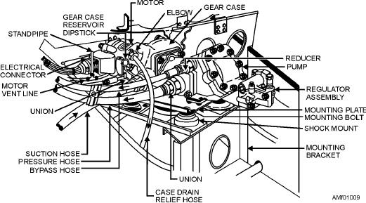
Figure 1-9 is an example of an installation diagram.
procedure used when you are determining what unit is
This is a diagram of the motor-driven hydraulic pump
causing a particular system malfunction. The MIM for
installation. Installation diagrams show general loca-
each aircraft generally provides troubleshooting aids
tion, function, and appearance of parts and assemblies.
that encompass the following seven steps:
On some installation diagrams, letters on the principal
1. Conduct a visual inspection
view refer to a detailed view located elsewhere on the
diagram. Each detailed view is an enlarged drawing of a
2. Conduct an operational check
portion of the system identifying each of the principal
3. Classify the trouble
components for purposes of clarification. Diagrams of
this type are invaluable to maintenance personnel in
4. Isolate the trouble
identifying and locating components. Installation
5. Locate the trouble
diagrams will aid you in understanding the principle of
operation of complicated systems.
6. Correct the trouble
Q1-12.
What type of diagram is useful for showing
7. Conduct a final operational check.
the relationship of components of a system
Figure 1-9.--Installation diagram of a motor-driven hydraulic pump.
1-11