
in the aircraft. They do locate components with respect
by an actuating system may be caused by difficulties in
to each other within the system. Various components
the power system. A symptom indicated by a
are indicated by symbols in schematic diagrams, while
component of the power system may be caused by
drawings of the actual components are used in the
leakage or malfunction of one of the actuating systems.
installation (pictorial) diagrams. The symbols used in
When any part of the hydraulic system becomes
the schematic diagrams conform to the military stan-
inoperative, use the diagrams in conjunction with the
dard mechanical symbols provided in MIL-STD-17B-1
checkout procedures provided in the aircraft MIM.
and MIL-STD-17B-2. Most manufacturers improve
Possible causes of trouble should always be eliminated
upon these basic symbols by showing a cutaway
systematically until the pertinent cause is found. No
portion on each component. These cutaways aid in
component should be removed or adjusted unless there
clarifying the operation of that component. You should
is a sound reason to believe the unit is faulty.
be able to trace the flow of fluid from component to
There are two classes of diagrams you will be
component. On most diagrams of this type, an
concerned with in gaining a complete knowledge of a
uncolored legend or different colors are used to
specific system. These are the schematic and
represent the various lines. The legend identifies the
installation diagrams. A diagram, whether it is a
lines in relation to their purpose and the mode of
schematic diagram or an installation diagram, may be
operation being represented. Each component is further
defined as a graphic representation of an assembly or
identified by name, and its location within the system
system.
can be determined by noting which lines lead into and
out of the component.
Schematic Diagrams
Since many systems are electrically controlled, you
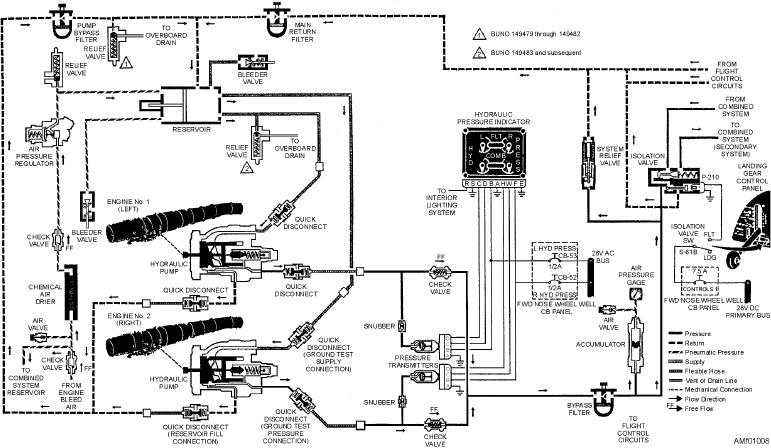
Figure 1-8 is another example of a schematic
should be capable of reading the electrical portion of a
diagram. Diagrams of this type do not indicate the
schematic diagram. Knowledge of the electrical
actual physical location of the individual components
symbols and the use of a multimeter in making voltage
Figure 1-8.--Hydraulic system schematic.
1-10