
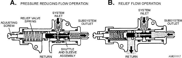
Figure 11-17.--Pressure-reducing valve operational schematic.
which causes the shuttle to move to the left after
the direction of flow. This movement uncovers ports,
allowing fluid to flow through the fuse.
reaching a specified pressure, thus closing off the
normal system. The valve will stay in this position
The movement of the locking piston also causes a
until the subsystem pressure is lowered, at which time
lock spring to release the piston subassembly stop rod,
the shuttle will move to its prior position and allow the
thus allowing the piston to be displaced by fluid from
required amount of pressurized fluid to enter the
the secondary flow. If the flow through the fuse
subsystem. During normal operation of the subsystem,
exceeds a specified amount, the piston, moving in the
the pressure-reducing valve continuously meters fluid
direction of flow, will block the ports originally
to the subsystem.
covered by the locking piston, thus blocking the flow
of fluid.
HYDRAULIC FUSES
Any interruption of the flow of fluid through the
fuse removes the operating force from the lock piston.
A hydraulic fuse is a safety device. Fuses may be
This allows the lock piston spring to return the piston to
installed at strategic locations throughout a hydraulic
the original position, which resets the fuse.
system. They are designed to detect line or gauge
rupture, fitting failure, or other leak-producing failure
Q11-15. To relieve pressure created by thermal
or damage.
expansion of the fluid, a system that has a
balanced poppet-type selector valve must also
One type of fuse, referred to as the automatic
incorporate what other type of valve?
resetting type, is designed to allow a certain volume of
fluid per minute to pass through it. If the volume
Q11-16. The poppets of a poppet-type selector valve
passing through the fuse becomes excessive, the fuse
are actuated by what means?
will close and shut off the flow. When the pressure is
Q11-17. When all four of the poppets of a poppet-type
removed from the pressure supply side of the fuse, it
selector valve are held firmly seated by the
will automatically reset itself to the open position.
springs and there is no fluid flow, the valve is
Fuses are usually cylindrical in shape, with an inlet
in what position?
and outlet port at opposite ends, as shown in figure
Q11-18. External leakage from a poppet-type selector
11-18. A stationary sleeve assembly is contained
valve could be caused by what condition?
within the body. Other parts contained within the body,
Q11-19. Currently, what type of selector valve is the
starting at the inlet port, are a control head, piston and
most durable and trouble-free?
piston subassembly stop rod, a lock spring, and a lock
piston and return spring.
Q11-20. The slide-type selector valve has raised,
machined portions that are known by what
Fluid entering the fuse is divided into two flow
term?
paths by the control head. The main flow is between
the sleeve and body, and a secondary flow is to the
Q11-21. A slide-type selector valve has three grooves
piston. Fluid flowing through the main path exerts a
at the end next to the eye. The grooves are
known by what term?
force on the lock piston, causing it to move away from
11-20